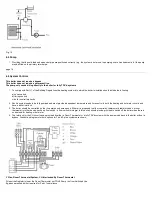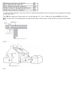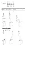
from the boiler and include any branches (
).
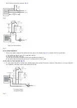
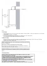
Fig. 9
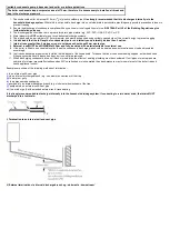
Fig. 10
6.4 Low Head Installation
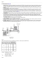
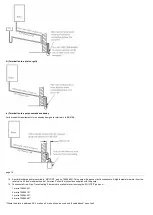
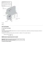
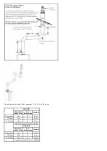
1. Using a close couple arrangement the minimum head is as shown in the diagrams (
&
) subject to the following conditions:
a) The pump being adjusted to give a 20°C drop across the boiler.
b) The pump must be fitted on the flow.
c) The pump must be fitted in accordance with the pump manufacturer's instructions.
d) The open vent pipe must be taken up from a tee in a horizontal section of the flow pipe.
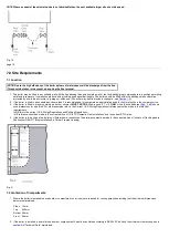
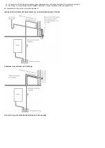
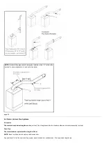
An alternative Low Head Installation (
)
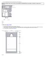
2. For heads below 400mm then a combined vent and feed pipe may be connected. This must be a minimum of 22mm diameter. It is recommended that
an air separator is fitted when using a combined feed and vent pipe.
Fig. 11
Содержание Main Heat 12
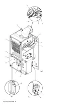
Страница 8: ...Fig 3 Fig 4 Fig 5 Fig 6...
Страница 38: ...Example 1 Example 2 Example 3...
Страница 40: ...Fig E Fig F...
Страница 51: ...Fig 31 Fig 32 Fig 33...
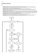
Страница 55: ...Fig 35 Fig 36 page 39 12 2 Checking the Combustion 1 Follow the flow chart opposite...
Страница 56: ......
Страница 63: ...Fig 45 Fig 46...
Страница 66: ......
Страница 69: ...Fig 55 Fig 56 Fig 57 Fig 58...
Страница 72: ...page 52...
Страница 74: ...page 54...
Страница 75: ...DRY FIRE...
Страница 76: ...page 55 IGNITION LOCKOUT...
Страница 77: ...page 56 OVERHEAT LOCKOUT...
Страница 78: ...page 57 FAN LOCKOUT NOTE The fan is supplied with 325 Vdc...
Страница 80: ...warranty This does not affect the customer s statutory rights page 62...
Страница 82: ...page 63...


