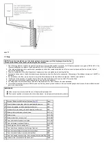
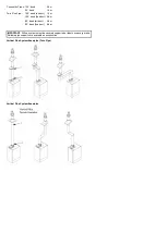


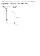

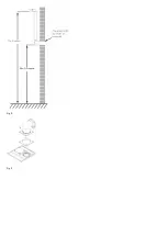


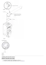
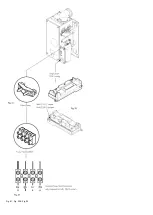

Fig. D
Flue Length - Worked Example Main 30 Heat
In
Above an additional 93° elbow and pair of 45°
elbows have been included in the 70Ø exhaust.
Also 3 straight extension pieces have been used.
To calculate total length:-
Length of 70Ø supplied in kit =
1 metre
3 x 1 metre Extensions =
3 metres
1 x 93° Elbow =
1 metre
2 x 45° Elbow =
1 metre (0.5 metres each)
Total 70Ø =
6 metres
After consulting the table in
that the concentric flue could be up to approximately 3.25
metres long.
page 28
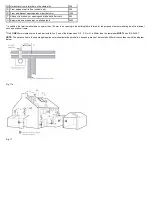
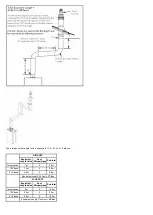
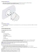
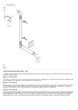
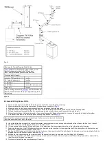
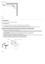
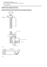
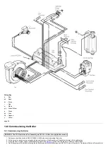
9.3 General Fitting Notes - P.D.K.
1. Cut a hole in the external wall which the horizontal concentric flue assembly will pass through.
2. When completed the terminal must be at least 2 metres above ground level (
3. Measure and cut to size the concentric assembly and any extensions that are being used.
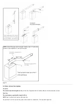
4. Insert the concentric assembly through the hole from outside the building and mark the position of the flue trim securing holes.
5. Drill and plug the wall to accept the flue trim securing screws, and re-insert the concentric assembly through the wall.
6. Connect any extensions that are being used to the concentric assembly. Engage the extension or concentric assembly in the boiler flue elbow.
7. Fit the boiler flue elbow to the boiler top panel, ensuring the gasket is in place (
Ensure that the concentric assembly is horizontal and that the external air inlet is to the bottom.
Any extensions should fall back to the boiler.
8. Use suitable brackets to support the concentric assembly and any extensions, and make good inside and outside. Secure the flue trim to the wall.
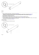
9. The 70Ø exhaust can now be fitted to the spigot at the terminal end.
10. If it is necessary to shorten the 70Ø exhaust or any of the extensions, the excess material must be cut from the plain end of the pipe.
11. Determine the position of the 70Ø exhaust and mark on the wall a suitable position for the support bracket. Drill and plug the wall. If extensions are
being used, a support bracket is supplied in each kit.
12. Engage the M6 threaded part of the mounting bolt in the boss on the support bracket. Using the bracket for leverage, screw the mounting bolt into the
plugged hole until the bracket is secure and level (
13. Slacken the two screws securing the retaining strap to the bracket, and pivot the strap aside to allow fitting the 70Ø exhaust.
14. Complete the installation of the 70Ø exhaust, securing in the brackets. Fit the 93° elbow and plume outlet. Ensure the plume outlet is at least 45° to
the wall and that the 'peak' is uppermost.
15. Continue with installation and commissioning of the boiler.
Содержание Main Heat 12
Страница 8: ...Fig 3 Fig 4 Fig 5 Fig 6...
Страница 38: ...Example 1 Example 2 Example 3...
Страница 40: ...Fig E Fig F...
Страница 51: ...Fig 31 Fig 32 Fig 33...
Страница 55: ...Fig 35 Fig 36 page 39 12 2 Checking the Combustion 1 Follow the flow chart opposite...
Страница 56: ......
Страница 63: ...Fig 45 Fig 46...
Страница 66: ......
Страница 69: ...Fig 55 Fig 56 Fig 57 Fig 58...
Страница 72: ...page 52...
Страница 74: ...page 54...
Страница 75: ...DRY FIRE...
Страница 76: ...page 55 IGNITION LOCKOUT...
Страница 77: ...page 56 OVERHEAT LOCKOUT...
Страница 78: ...page 57 FAN LOCKOUT NOTE The fan is supplied with 325 Vdc...
Страница 80: ...warranty This does not affect the customer s statutory rights page 62...
Страница 82: ...page 63...