


Water Central Heating Systems (see
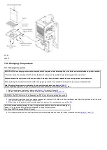
5. Complete the label supplied with the inhibitor and attach to the inside of the boiler case. Detail of system treatment should be added for future
reference.
6. Turn the gas supply on and purge according to in GB BS 6891 and in IE I.S. 813 "Domestic Gas Installations"
.
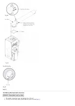
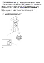
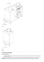
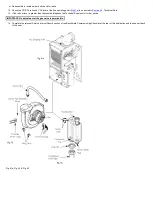
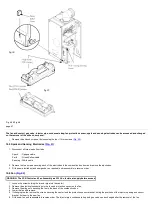
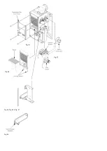
7. Remove the top RH securing screw and hinge down the PCB housing to gain access to the gas service cock (see
). Turn the gas service cock
anticlockwise to the ON position and check for gas tightness up to the gas valve (
NOTE
: The 12,15,18 & 24 are self-regulating dependent upon the system load. The 30 will modulate between inputs of 33.76kW and 10.3kW.
The 30 input is factory set at 24.5kW and can be altered to 33.76kW - see
No adjustment of the gas valve is permissible.
IMPORTANT
: The combustion for this appliance has been checked, adjusted and preset at the factory for operation on the gas type
specified on the appliance data plate. No measurement of the combustion is necessary. Do not adjust the air/gas ratio valve.
8. Having checked:
That the boiler has been installed in accordance with these instructions.
The integrity of the flue system and the flue seals.
The integrity of the boiler combustion circuit and the relevant seals.
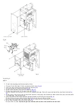
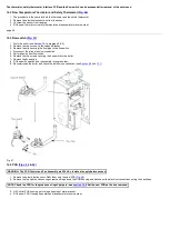
Fig. 34
Содержание Main Heat 12
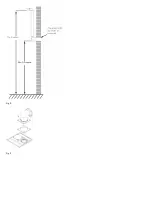
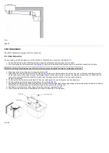
Страница 8: ...Fig 3 Fig 4 Fig 5 Fig 6...
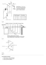
Страница 38: ...Example 1 Example 2 Example 3...
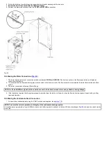
Страница 40: ...Fig E Fig F...
Страница 51: ...Fig 31 Fig 32 Fig 33...
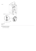
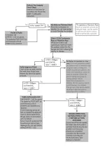
Страница 55: ...Fig 35 Fig 36 page 39 12 2 Checking the Combustion 1 Follow the flow chart opposite...
Страница 56: ......
Страница 63: ...Fig 45 Fig 46...
Страница 66: ......
Страница 69: ...Fig 55 Fig 56 Fig 57 Fig 58...
Страница 72: ...page 52...
Страница 74: ...page 54...
Страница 75: ...DRY FIRE...
Страница 76: ...page 55 IGNITION LOCKOUT...
Страница 77: ...page 56 OVERHEAT LOCKOUT...
Страница 78: ...page 57 FAN LOCKOUT NOTE The fan is supplied with 325 Vdc...
Страница 80: ...warranty This does not affect the customer s statutory rights page 62...
Страница 82: ...page 63...