


21
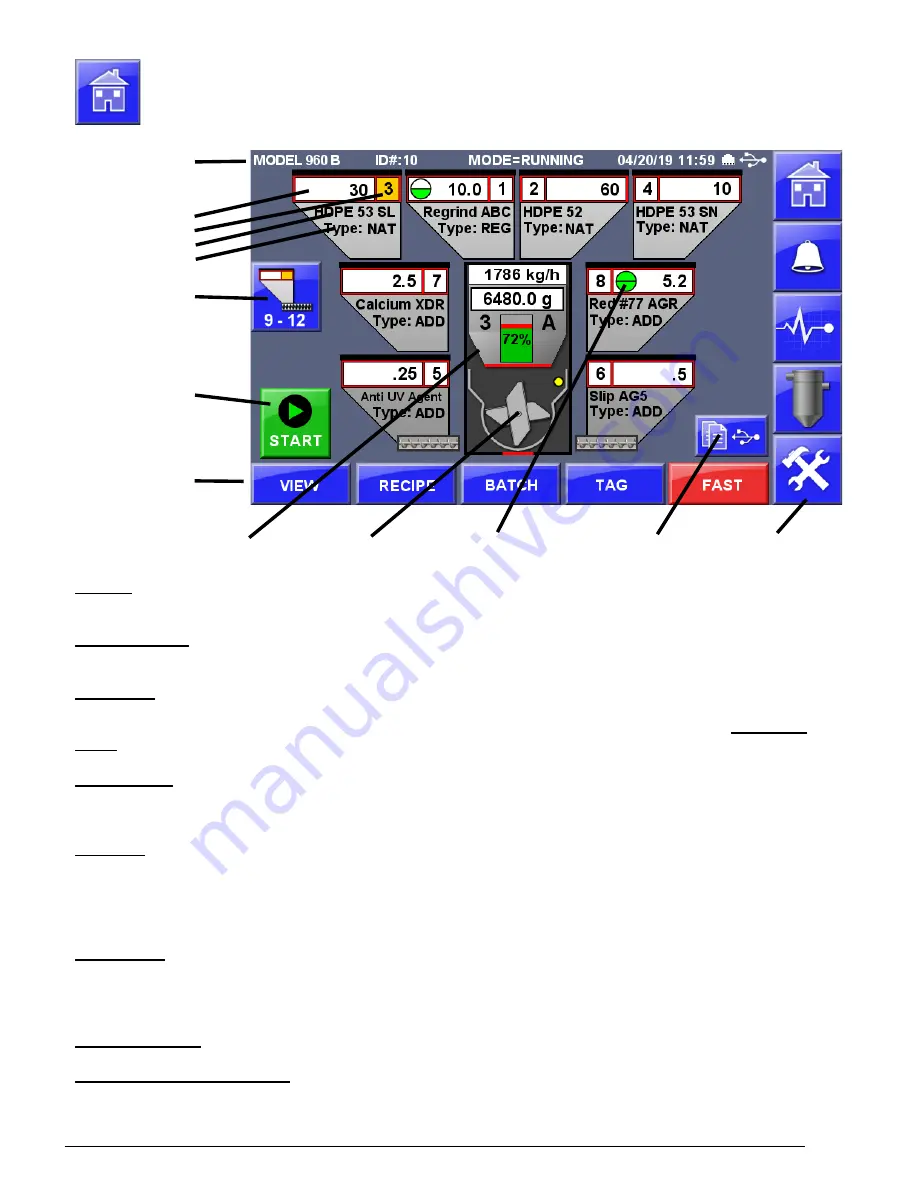
Home Screen
Title Bar
Component
Setpoint
Hopper number
Name
Type
Hoppers
9 - 12
START/STOP
Button
Specialized
Operations
Weigh Bin
Mix Chamber High / Low Limits Print Center
Nav bar
Title Bar
- The title bar displays: Model, current Operating Mode (blender, dispenser or Totalizer), date and time, Ethernet
and USB status. Operating Modes are: WAITING, blender is idle (stopped or mix chamber sensor covered).
Navigation Menu
– (Nav bar) Located along the right side of the screen, these buttons allow quick navigation to
frequently used and top-level screens. The middle three buttons are soft buttons that can be changed or removed.
Component
- This area displays the current configuration of each component (hoppers and feeders), component setpoint,
material name, component type, visible alarms, dispensing indicators (dispensing component hopper number turns yellow
when dispensing). Touch any anywhere on a hopper to access more detail on the individual component.
High / Low
Limits
, when enabled by the SE or SL component parameters, allow setting a high or low limit on the component.
Hoppers 9 - 12
- The main Home Screen displays hoppers 1 through 8. Hoppers 9 through 12 are displayed on a second
screen accessible by pressing this button. To return to viewing hoppers 1- 8, press this button again. During operation, the
display will automatically toggle to show hoppers that are currently operating.
Weigh Bin
– Displays current throughput per hour, current weight in weigh bin, the current dispensing component (hopper
number and type displayed when that component is dispensing), percentage completed of the cycle (green area) and the
portion that is currently dispensing displayed in red. The weigh bin dump flap status (red when closed, green when open).
Tap for Weigh Bin Setup options (password protected), Weigh Limits, Vibration Control, Control Times, Alarms, End
Empty/End Full, Weigh Bin Close (twice or once), Weigh Bin Calibration. Press to enter the Weigh Bin Setup screen.
Mix Chamber
– The mix chamber displays the mix chamber level sensor (yellow when cover, gray when uncovered) and
mix motor status (idle or rotating). Below the mix chamber the Flow Control Valve (FCV) status is displayed (red when
closed, green when open). Tap for Mix Chamber Setup options, Mixer Control, Sensor Blow off, Mix Chamber Alarms.
Press to enter the Mix Chamber Setup screen.
Start / Stop Button
- Main Start and Stop Control Button of the Blender. Also see Automated Control.
Specialized Operations Buttons
- When enabled and made visible Specialized Operations Buttons allow access to
specific functions of the blender including View of current totals, Internal Recipe Database, Batch Mode, Tag Information
and FAST mode.
Содержание Weigh Scale Blender 4088
Страница 6: ...6 EC Declaration of Conformity ...
Страница 10: ...10 Blender Parts Key ...
Страница 13: ...13 ...
Страница 104: ...104 Technical Drawings ...
Страница 105: ...105 ...
Страница 106: ...106 ...
Страница 107: ...107 ...
Страница 108: ...108 ...
Страница 109: ...109 ...
Страница 110: ...110 ...
Страница 111: ...111 ...
Страница 112: ...112 ...
Страница 113: ...113 ...
Страница 114: ...114 ...
Страница 115: ...115 ...
Страница 116: ...116 FCA INSTALLATION DIAGRAM ...
Страница 117: ...117 WSB 4088 IO wiring diagram 120V ...
Страница 118: ...118 D WSB E0001 Electrical Diagram WSB Export Single Phase ...
Страница 119: ...119 D WSB E0002 Electrical Diagram WSB Export 3 Phase ...
Страница 120: ...120 D WSB E0003 Electrical Diagram WSB Export 1800 3 Phase ...
Страница 121: ...121 D WSB E0004 Electrical Diagram WSB Export Maxibatch ...
Страница 122: ...122 WSB Single Phase Motor Safety Circuit WSB 3 Phase Motor Safety Circuit WSB 18 3 Phase Motor Safety Circuit ...
Страница 123: ...123 D WSB P0001 Pneumatic Diagram WSB with Non Removable Hoppers ...
Страница 124: ...124 D WSB P0002 Pneumatic Diagram WSB with Removable Hoppers ...
Страница 125: ...125 ...
Страница 143: ...143 Flexbus Lite Wiring Diagrams ...
Страница 144: ...144 ...
Страница 145: ...145 ...
Страница 146: ...146 Flexbus Lite Component Map ...


