


6
46-605 Flanged External Cage Float Actuated Liquid Level Switches
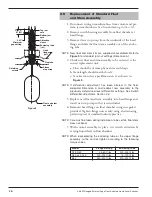
Internal Circuit
(Right) Switch
1
2
3
Load
Load
Line
4
5
6
Internal Circuit
(Left) Switch
Load
Load
Close on high level
Close on high level
Common
Common
Close on low level
Close on low level
Line
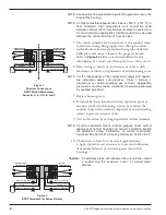
Figure 2
Terminal Connections
DPDT Switch Mechanism
Series B, C, D, F, R, 8, and 9
NOTE: Housing must be grounded via protective ground screw in the
base of the housing.
NOTE: On high temperature applications (above +250° F [+121° C] in
float chamber), high temperature wire should be used
between control and first junction box located in a cooler area.
On non-hazardous applications, flexible conduit may be used
between the control and the first junction box.
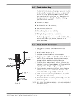
5. The switch terminals are located next to the conduit outlet
to facilitate wiring. Bring supply wires through conduit
outlet. Route extra wire around enclosing tube under the
baffle plate and connect them to the proper terminals.
Refer to
Figure 2 or 3
or your switch bulletin for this
information. See
Switch and Housing Reference, Section 6.2.2.
6. Dress wiring to ensure no interference or contact with
movement of switch, or replacement of switch housing cover.
NOTE: It is the responsibility of the customer to comply with applica-
ble installation codes and practices. Class I, Division 1
locations may contain explosive gas mixtures. Appropriate
precautions must be taken. Installation should be performed
by qualified personnel.
7. Replace housing cover.
8. If control has been furnished with an explosion proof or
moisture proof switch housing, it must be sealed at the
conduit outlet with a suitable compound or non-hardening
sealant to prevent entrance of air.
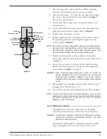
9. Test switch action by varying liquid level in float chamber.
NOTE: If switch mechanism fails to function properly, check vertical
alignment of control housing and consult installation bulletin
for additional wiring information on switch mechanism
furnished. See
Switch and Housing Reference, Section 6.2.2.
10. Check cover to base fit to be certain gasketed joint
is tight. A positive seal is necessary to prevent infiltration
of moisture-laden air or corrosive gasses into switch
housings.
Caution:
In hazardous areas, do not power the unit until the conduit
is sealed and the enclosure cover is screwed down
securely.
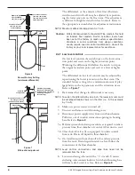
Figure 3
DPDT Terminals for Series HS only
Internal
Circuit
(Right) Switch
1
2
3
Load
Load
Close on low level
Common
Close on high level
Line
4
5
6
Internal Circuit
(Left) Switch
Load
Load
Close on low level
Common
Close on high level
Line


