


46-605 Flanged External Cage Float Actuated Liquid Level Switches
13
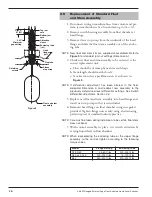
11. Check float to be certain it is buoyant in the liquid (float
chamber or vessel must have adequate liquid level). If float
is determined to be filled with liquid, or it is collapsed, it
must be replaced immediately.
Caution: Do not attempt to repair a float.
See
Replacement of
Standard Float and Stem Assembly, Section 2.5.
If all components in the control are in operating condition,
the trouble is likely located external to the control. Repeat
inspection of external conditions as previously described.
NOTE: If difficulties are encountered which cannot be identified,
consult the factory or your local representative for assistance.
A complete description of the trouble should be provided
along with information concerning your piping and mounting
arrangement, plus a description of your operating sequence.
Sketches or photographs showing the installation are also
beneficial.
When inquiring about your control, be certain to always
specify the complete Model and Serial numbers.
4.0
Preventive Maintenance
Periodic inspections are necessary to keep your level
control in good working order. This control is a safety
device to protect the valuable equipment it serves. A
systematic program of “preventive maintenance” must be
implemented when the control is placed into service. If
the following sections on “what to do” and “what to avoid”
are observed, your control will provide reliable protection
of your equipment for many years.
4.1
Recommended Practice
4.1.1 Keep control clean
Be sure the switch housing cover is always in place on the
control. This cover is designed to keep dust and dirt from
interfering with switch mechanism operation. It also pro-
tects against damaging moisture and acts as a safety feature
by keeping bare wires and terminals from being exposed.
Should the housing cover or any seals become damaged or
misplaced, obtain a replacement immediately.
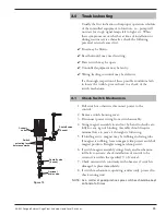
4.1.2
Inspect switch mechanisms, terminals, and
connections monthly
1. Dry contact switches should be inspected for excessive
wear on actuating lever or misalignment of adjustment
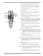
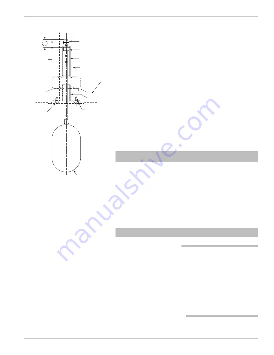
A
0.03"
Minimum
gap setting
Top jam
nuts
Bottom jam
nuts
Attraction
sleeve
Enclosing tube
(ref.)
Stop tube
Sleeve
stop strap
Retaining
screws
Float and stem
assembly
Head
flange
(ref.)
Figure 11


