


4
46-605 Flanged External Cage Float Actuated Liquid Level Switches
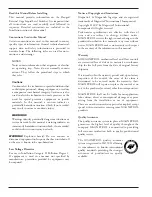
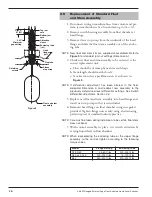
Optional
drain valve
Shutoff valve
(if used)
Conduit
outlet
Switch
actuating level
lreference marks
Shutoff valve
(if used)
Typical Piping Arrangement
1.0
Installation
Caution:
If equipment is used in a manner not specified by manu-
facturer, protection provided by equipment may be
impaired.
1.1
Unpacking
Unpack the instrument carefully. Inspect all units for
damage. Report any concealed damage to carrier within
24 hours. Check the contents against the packing slip and
purchase order. Check and record the serial number for
future reference when ordering parts.
Serial # _____________________________________
Caution:
Do not discard the shipping container until all parts are
accounted for.
1.2
Critical Alarm Function
It is recommended that for critical alarm functions, an
additional level switch be installed as a high–high or low–
low level alarm for maximum protection.
1.3
Piping
An instruction tag secured to the control gives dimensional
data on switch actuating levels referenced from center line
of upper side tank connection. Position control so that
actuating levels correspond with the desired liquid level
trip points in process vessel.
Use pipe of sufficient strength to support the control. If
necessary, provide a stand or hanger to help support its
weight. All piping should be straight and free of “low
spots” or “pockets” so that lower liquid line will drain
towards the vessel and upper vapor line will drain toward
the control. Shut-off valves are recommended for installa-
tion between the vessel and the control. If control is to
be used with a low temperature liquid (one which will
“boil” in the float chamber if outside heat is absorbed),
the chamber and piping should be insulated. Such
boiling in the chamber will cause false level indications.
Caution:
DO NOT INSULATE SWITCH MECHANISM HOUSING.
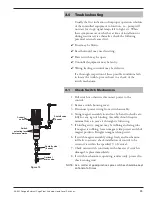
For controls equipped with pneumatic switch assemblies,
consult bulletin on mechanism furnished for air (or gas)
piping instructions.


