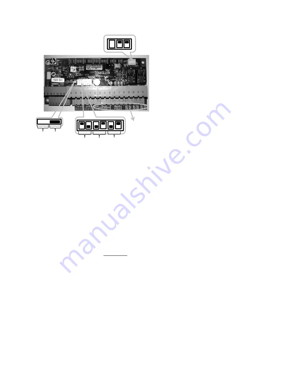
Installation
9
Figure 13: TerMag Board Switch Configuration
PM Drive Setup Procedure
1. Verify that the drive is in PM Mode for
Drive Mode in U9.
2. Enter the measured building voltage
going into the drive in the ‘Input L-L
Volts’ (A4)
3. Enter your motor data from the motor
nameplate into Sub-menu A5: Motor
ID, rated motor power, rated motor
volts, rated motor current, rated motor
poles, and rated motor speed.
a.
𝑚𝑜𝑡𝑜𝑟 𝑝𝑜𝑙𝑒𝑠 =
120∗𝑚𝑡𝑟 𝑓𝑟𝑒𝑞
𝑟𝑎𝑡𝑒𝑑 𝑚𝑡𝑟 𝑟𝑝𝑚
If your motor speed and motor
poles are entered correctly,
motor frequency on nameplate
and the ‘Rated Excit Freq’ in
the D2 sub-menu should be
the same
4. Setup both
‘Encoder Pulses’ and ‘Enc
PPR Low’ in the A1 sub-menu using
one of the following method: a
(preferred), b, or c.
NOTE:
Encoder Pulses (A1) is set
higher than the PPR on the encoder
nameplate (in this case 1024 PPR)
because the encoder shaft is mounted
on a rider wheel that sits on the rotor;
1 revolution of the rider wheel doesn’t
equate to 1 revolution of the motor
a. Ropes off PPR (preferred):
i. with
ropes removed
from/off
sheave, perform
an Open Loop Alignment
on page 12.
ii. After the alignment, enter
the number in Measured
PPR (D1) into the Encoder
Pulses (A1).
iii. Then run the motor at
contract speed and look at
the Measured PPR (D1)
while motor is rotating at
contact speed with ropes
OFF
iv. The number in Measured
PPR (D1) while motor was
rotating at contract speed
should be entered to
Encoder Pulses (A1)
NOTE: if this is done, step
8 in PM
on page 10
doesn’t need to be done.
NOTE: Measured PPR
(D1) at high speed is more
accurate than at low speed.
b. Ropes on PPR estimate:
i. Select from Table 2 (page
10) the number of encoder
pulses that correspond to
the motor frame you have.
Enter that number as the
Encoder Pulses in the A1
menu
SW3
SW2
Switch
configuration
description
on board
Z
sing
A
diff
B
diff
12V
DC
5V
DC
SW1
1
2
3


