background image

Installation Procedure

Step 1:

After obtaining the required space and
mounting hold dimensions required,
release the mounting sleeve from the unit
by pressing inward on the sides of the unit
and sliding the mounting sleeve off the
unit.
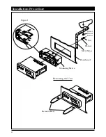
Insert the mounting sleeve into the hole
on the dashboard. Secure it by bending
the tabs inward as shown in fig 1. Select
the appropriate tab according to the
thickness of the dashboard.

Step 2:

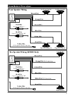
Bring the power, ground, antenna and
speaker wires through the center of the
mounting sleeve. Make all the speaker
and power connections to the main har-
ness supplied with the unit. Refer to the
“wiring” section of this unit for proper
connection. After all the connections
have been made and are correct, plug the
harness and the antenna cable into the
mating plugs located on the rear of the
unit.

Step 3:

Turn on the ignition key and do a pre-
installation check of all the functions with
the unit out of the dashboard to make
sure that everything is operating properly
before final installation.

Step 4:

Securely attach the rear support strap pro-
vided to the rear of the unit with the fas-
teners provided. Bend the strap to allow
the unit to slide into it’s mounting sleeve.
Reach up behind the unit and grab the
strap while sliding the unit into the
mounting sleeve until it snaps into place.
Secure the end of the strap to a solid por-
tion of the dashboard structure or the fire
wall.

Removing the Unit:

In the event that the unit requires
removal from it’s mounting location,
repeat the following procedures.

A. Release the rear support strap.
B. Insert the keys provided into the slot
on both sides of the chassis until locked.v
(snapped into place)

C. Pull on the keys with equal pressure to
release and remove the unit from the
mounting sleeve.
D. Disconnect the wire harness and the
antenna.

3

M9000/M9050H/-2  08/04/00  7:57 AM  Page 3

Содержание M9000

Страница 1: ...NCE VOL POWER AUTO STORAGE PRESET MEMORY AUTO STOP CASSETTE FAD SEEK AS BAND F C 1 2 3 4 5 6 TUNE UP DOWN PLL SYNTHESIZER TUNER SEEK FM 1 2 3 AM ST CH EJECT TREB BASS VOL POWER BAL PULL AUTO STORAGE P...

Страница 2: ...____________________ 2 Introduction Mechanical Installation Most all automobiles trucks and vans pro vide a mounting location somewhere in the fascia of the dashboard or center con sole to install a r...

Страница 3: ...ar of the unit Step 3 Turn on the ignition key and do a pre installation check of all the functions with the unit out of the dashboard to make sure that everything is operating properly before final i...

Страница 4: ...Installation Procedure 4 Nut Washer Sheet Metal Screw Metal Strap Dashboard Mounting Sleeve Removal Keys Removing the Unit Figure 1...

Страница 5: ...nition key Use a test light or volt meter to locate a connection point at the fuse block Note If your are replacing a factory installed radio this wire will exist in the wires that connected to the ol...

Страница 6: ...nnect the white wire to both Right speaker Negative wires Blue Wire Connect the blue wire to the Right Rear speaker Positive wire Wiring Two Speakers M9000 Only Fader Control Deleted Brown Wire Connec...

Страница 7: ...Plug From Radio Yellow Wire 12 Output for Power Antenna Pink Wire Connect to Battery Red Wire Connect to Ignition 12V Right Speaker Left Speaker Brown Wire Gray Wire White Wire No Connection Blue Wire...

Страница 8: ...els To select the AM or FM radio band press the BAND button FM1 FM2 FM3 AM1 or AM2 will appear in the display ST will appear in the display when the tuner is receiving a stereo FM signal 3 How to Tune...

Страница 9: ...s played in the digital display area To con tinue seeking stations the SEEK button will have to be pressed again Controlling the Sound Adjust the following controls to suit your listening preference V...

Страница 10: ...and right speaker output to suit your listening taste Balance Control M9050H Only Pull and rotate the balance control left or right to achieve the desired left and right speaker output to suit your li...

Страница 11: ...e time of installation Address each category and repeat the procedures listed to cor rectly perform the programming Setting the Clock 1 With the unit on make sure the display is showing the clock by p...

Страница 12: ...number appear in the right hand corner of the dis play When the station is memorized the sound will mute for a moment and then return to normal 5 Repeat the procedure to store up to 6 radio stations f...

Страница 13: ...the group paus ing for 5 seconds at each station When the unit pauses on a station you want to listen to simply press and release the AS button again to stop the automatic scan ning feature 1 Take up...

Страница 14: ...or indicator in the display To rewind the tape press the PROG button with the or that is opposite from the or indica tor in the display Press the button in until it locks To release the button lightly...

Страница 15: ...me If you record your own tapes on high quality CRO2 or metal tape you should clean the head about once a month Specifications AM FM Tuner FM Frequency Range 87 5 108 1MHz AM Frequency Range 520 1720K...

Страница 16: ...ch cost are the sole responsibility of the purchaser This warranty does not cover the cabinet appearance items or accessories used in connec tion with this product or any damage to recording or record...

Отзывы: