RS 350 M / RS 400 M / RS 500 M / RS 350 MW / RS 400 MW / RS 500 MW
EN
www.magmaweld.com
20
USER MANUAL | MANUAL DO UTILIZADOR | KULLANIM KILAVUZU
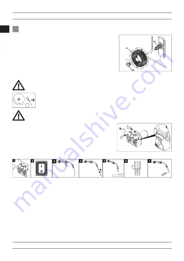
3.4 Loading The Wire Spool And Hreading The Wire
• Unscrew the spool support nut. Place the MIG/MAG wire spool through the spool support and
screw the spool support nut tightly. (Figure 19).
• Run the wire through the wire entry guide without releasing the wire onto the reels and push
it through the reels into the torch (Figure 20).
• Press the pressure rollers and raise the pressure lever.
(1)
• Operate the machine by turning the On / Off Switch to the “1” position.
(2)
• Press the trigger until the wire comes out of the torch tip, while observing that the welding wire reel turns freely, press and release the trigger
several times to check for any loosening of the winding.
(3)
If loosening and / or rewinding is observed, tighten the wire transport system screw
a little more.
• When the wire exits the torch tip, reattach the nozzle and contact nozzle to the torch.
(4)
• Set the appropriate wire print setting
(5)
by sliding the wire onto a board
(6)
and cut the wire end.
• Remove the welding wire from its place on the reel and cut the end of the welding wire with a side chisel.
Figure 19: Loading the Wire Spool
Figure 20: Feeding the Wire to Rollers
Screwing the spool support nut too tight may cause blockage of wire feeding. Screwing the spool support nut loose may
cause free turning of the wire spool after stopping wire feeding which may lead to feedability problems.
If the end of the wire is missed, the wire may be thrown out like a spring, causing harm to you and others.
Usage Operation
BOARD


