214143
9
Revision F
C
D
E
1030522
A
B
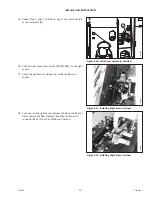
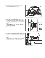
Figure 3.4: Installing Sensor Link Bracket
7.
Hold cable (E) in place, and replace bolt (C) and washer (D)
with bolt (MD #135671) and washer (MD #184705)
supplied in the kit.
8.
Install nut (A) (MD #152668) to secure the sensor link
bracket (B) to the float lever. Ensure washer (D) is between
bolt (C) and cable (E).
9.
Ensure cable eye (E) is not twisted, and then fully tighten
bolt (C).
1024211
A
B
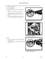
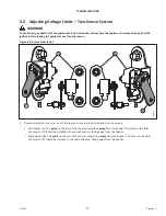
Figure 3.5: Right Sensor Assembly
10. Check if jam nuts (A) are tight against the two ball joints of
the right sensor assembly. If jam nuts are not secured,
tighten to 12 Nm (9 lbf·ft).
IMPORTANT:
Measurement (B) should be 50.4 mm (1 31/32 in.).
Incorrect measurement will lead to equipment damage.
1030471
A
B
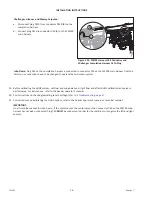
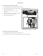
Figure 3.6: Right Sensor Assembly
IMPORTANT:
The sensor is to be installed with electrical connector (A)
facing down and sensor arm arrow (the pointed end) (B)
facing the combine.


