214143
23
Revision F
1016923
A
B
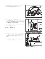
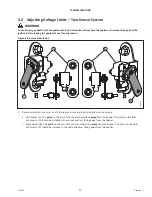
Figure 4.10: Optional Two-Sensor Kit
–
Right Sensor
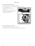
10. Loosen sensor mounting nuts (A).
11. Rotate sensor (B) clockwise to lower the voltage. Rotate
sensor counterclockwise to raise the voltage.
12. Check that the right sensor is at the correct high
voltage limit.
13. Tighten sensor mounting nuts (A).
1016102
A
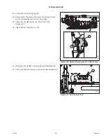
Figure 4.11: Float Indicator Box
14. Fully lower the header; float indicator (A) should be at
4
.
15. Check that both sensors are at the correct low voltage limit.


