background image

Mac Victor 2.0 Installation Operation Manual 042408.pdf - © 2008 Mac Victor Power, LLC.


 Page 5 of 23 


2 – PRODUCT OVERVIEW 


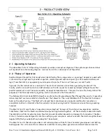
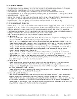
2.1  Operating Schematic 

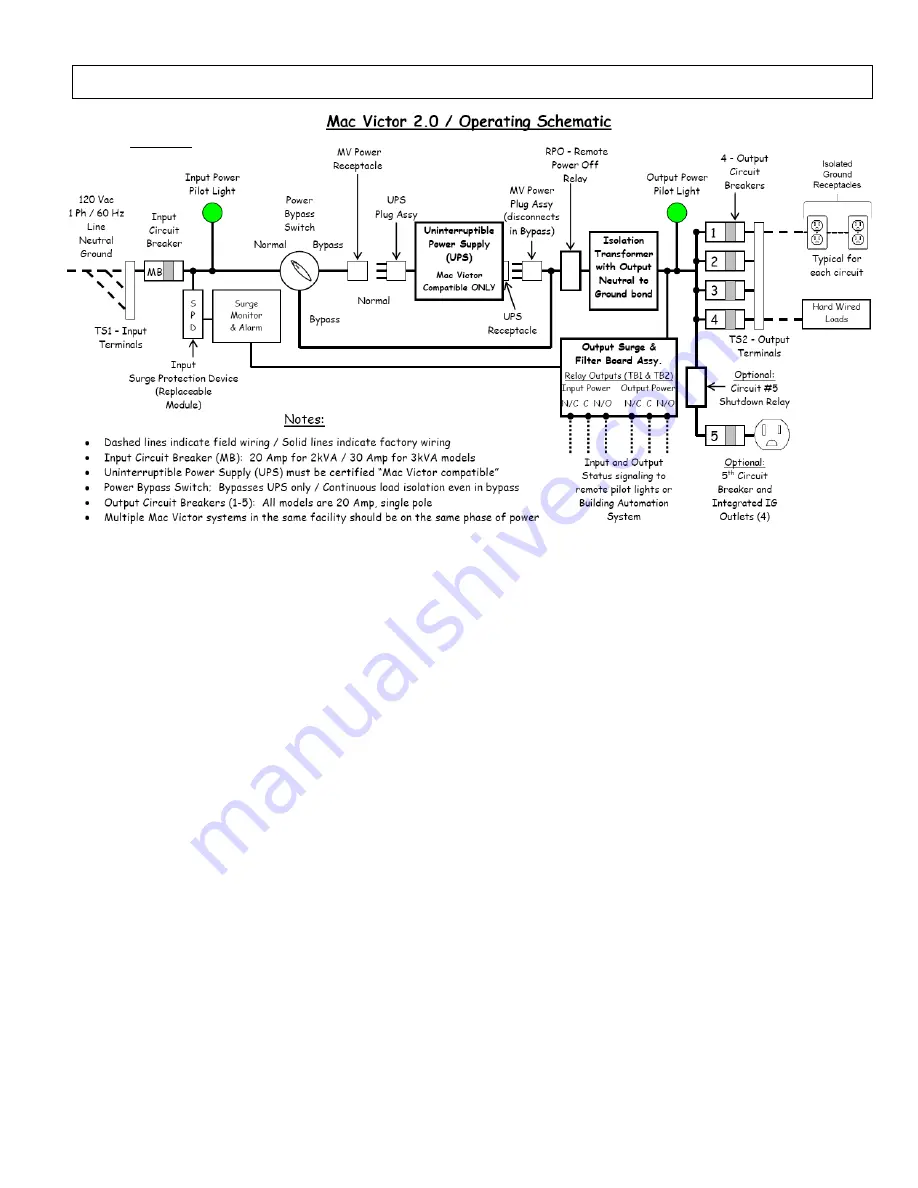
The above Mac Victor 2.0 Operating Schematic provides a conceptual diagram of the system operation and does 
not represent an actual wiring diagram.  See Section 2.4 for a Description of Operation. 

2.2  Theory of Operation  

Isolated Ground (hereafter IG) receptacles (identified by their orange color or an orange triangle) are used with 
critical electronic systems to provide a separate, isolated ground reference point (for data communication and 
logic) from the safety or equipment ground required to protect the circuit from over current faults. 
Typically, the IG conductors are run back to the electrical main service entrance grounding terminal of the 
facility, which can result in electrical disturbances on the IG conductor caused by induced voltages from other 
parallel conductors run in the same conduits, raceways and panelboards.  This practice can effectively defeat the 
purpose of the IG receptacles by injecting electrical noise onto the IG conductor. 

The National Electrical Code (NEC) allows for an alternative IG grounding method through the use of a “separately 
derived system” such as an isolation transformer that allows for the re-establishment of the Neutral to Ground 
bond on the output wiring.  This Neutral to Ground bond, also known as a newly derived Neutral, provides an 
acceptable location to terminate the IG conductor in lieu of wiring back to the main service entrance grounding 
terminal.   
The Mac Victor 2.0 constitutes a “separately derived system” because of the internal, low impedance, isolation 
transformer that has the Neutral and Ground output wiring bonded together.  All the conductors associated with 
the installation of IG receptacles (Line, Neutral, Ground, Isolated Ground) are designed to terminate at the Mac 
Victor 2.0 which is also designed to interface with plug and receptacle connections with the Uninterruptible Power 
Supply (UPS) that provides battery backup for the network. 
The Mac Victor 2.0 therefore provides a centralized system with both “clean” isolated ground power and battery 
backup power for critical electronic networks in addition to many other operational and maintenance benefits. 

Figure 2.1  

Содержание MVP-2KL

Страница 1: ...acles along with plug and receptacle connectivity for the Uninterruptible Power Supply UPS The mission of Mac Victor is to Expand Your Power by enhancing the return on investment of your Critical Elec...

Страница 2: ...ts 4 2 Location 4 3 Typical Elevation 4 4 Mounting Instructions 4 5 Wiring Diagram Mac Victor 2 0 4 6 Wiring Diagram Remote Power Off 4 7 Wiring Diagram Remote signaling of Input and Output power stat...

Страница 3: ...isconnect Switch may be required to de energize the equipment before servicing Service is to be performed by qualified personnel only See Installation Instructions before connecting to the supply The...

Страница 4: ...he UPS outlets Do not plug other equipment into the other UPS outlets except for the Mac Victor 2 0 plug assembly Equipment plugged into the other UPS outlets will not function in the bypass mode and...

Страница 5: ...acles by injecting electrical noise onto the IG conductor The National Electrical Code NEC allows for an alternative IG grounding method through the use of a separately derived system such as an isola...

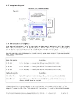
Страница 6: ...r off relay to the Isolation Transformer with neutral to ground bond Output Surge filter board assembly provides additional surge power protection and noise filtering Output Surge filter board assembl...

Страница 7: ...S IG Base Item Number Description MVP 2KS 2kVA Mac Victor 2 0 w straight blade UPS connectors NEMA 5 20P 5 20R MVP 2KL 2kVA Mac Victor 2 0 w locking blade UPS connectors NEMA L5 20P L5 20R MVP 3KL 3kV...

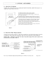
Страница 8: ...rical Code NEC NFPA 70 IG Suffix Isolated Ground receptacle option Integrated Isolated Ground Receptacles Option IG suffix includes 4 outlets and a 5th output circuit breaker The Integrated Isolated G...

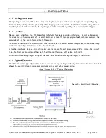
Страница 9: ...closet telecom equipment wall datacom room or other secure locations that are not accessible to the public To minimize the distance of branch circuit runs to the remote Isolated Ground receptacles ch...

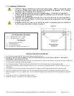
Страница 10: ...drivers etc Installation Steps Wood Stud Mounting 1 Locate 2 adjacent wooden studs 16 on center at the desired installation location 2 BE SURE TO ACCOUNT FOR THE HEIGHT OF THE UPS TO BE INSTALLED ON T...

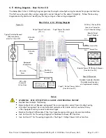
Страница 11: ...iring must be run in separate conduit from all output wiring All output wiring must be run in dedicated conduits or MC cable and not routed with any other equipment wiring to avoid induced voltages Re...

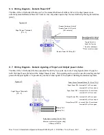
Страница 12: ...ower status pilot lights or to provide dry contact status signals to the inputs of Building Automation Systems Input Power Terminals TS 1 Remote Power Off Relay R1 Remote Power Off Switch maintained N...

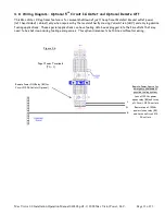
Страница 13: ...on AHJ and only in gasoline fueling applications These special applications can have fueling data boxes plugged into the IG outlets that may need to be shut down during fueling emergencies This option...

Страница 14: ...and latch the front hinged enclosure cover 5 Turn on the input power circuit breaker MB 1 located at the lower front right of the enclosure 6 The Input Power pilot should come on 7 Set the UPS Bypass...

Страница 15: ...2 0 Shelf with the front of the UPS facing to the left outlets and power cord facing the right 4 The UPS should be located on the shelf in a position that insures adequate rear ventilation of the UPS...

Страница 16: ...ecure any excess cabling 6 Insert the Safety Outlet Protector Plugs included on all open outlets on the back of the UPS 7 Follow the UPS power up procedures as outlined in the accompanying UPS Manual...

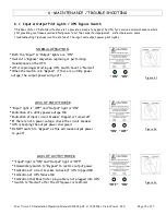
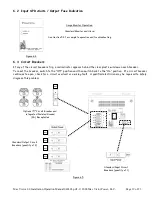
Страница 17: ...F1 on the Output Surge Filter Board Assembly Standard Surge Monitor Operation POWER ON green LED is ON during normal operation SERVICE red LED is OFF during normal operation SERVICE red LED is ON ind...

Страница 18: ...ing up UPS switch back to Normal When the Switch is in Bypass if there is a utility power outage the output power will go off LOSS OF INPUT POWER Input light is OFF and Output light is ON Indication o...

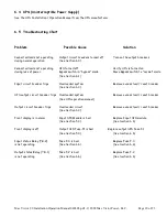
Страница 19: ...nd then switch back to the On position If a circuit breaker continues to open check for a circuit overload or a wiring fault A qualified electrician may be required to safely diagnose this problem Sur...

Страница 20: ...See Section 6 1 Input circuit breaker trips Overloaded system Remove excess load reset breaker See Section 6 3 UPS output circuit breaker trips Overloaded system Remove excess load reset breaker See...

Страница 21: ...fast acting 1 10 amp THOR 0603 0100 02 Mac Victor 2 0 Output SPD Filter Board Assy Located at the bottom of the enclosure TB 1 Relay Output Power TB 2 Relay Input Power Fuse F 2 Fuse F 3 Fuse F 1 Outp...

Страница 22: ...al Electrical Code U S Patent Pending Product Features Plug receptacle connectivity to many Uninterruptible Power Supply UPS vendors UPS battery bypass switch normal bypass Make before Break type Prov...

Страница 23: ...LLC 10500 Wakeman Drive Suite 105 Fredericksburg VA 22407 Phone 540 220 8116 Fax 540 242 7004 www MacVictor com Mac Victor and Expand Your Power are registered U S trademarks of Mac Victor Power LLC M...

Отзывы: