Mac Victor 2.0 Installation Operation Manual 042408.pdf - © 2008 Mac Victor Power, LLC.
Page 11 of 23
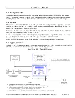
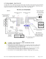
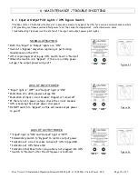
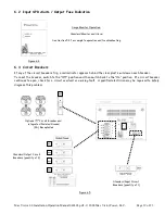
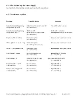
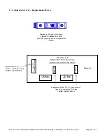
4.5 Wiring Diagram – Mac Victor 2.0
The below Mac Victor 2.0 Wiring Diagram provides the input and output wiring terminals for proper installation.
The factory wiring and other wiring components are not shown for the sake of simplicity. Follow these wiring
diagrams exactly and do not modify any factory wiring or other wiring components.
Green
White
Black
Typical Isolated Ground
(IG) receptacle
wired to Circuit #1
#12 AWG
White
#12 AWG
Black
#12 AWG
Green
OPTIONAL: only
when required by
local Electrical AHJ
Mac Victor 2.0 / Wiring Diagram
Input Power Terminals
(TS – 1)
Output Power Terminals
(TS – 2)
Isolated
Ground Bar
Equipment
Ground Bar
Notes:
WARNING: RISK OF ELECTRICAL SHOCK AND PERSONAL INJURY.
Dashed lines indicate field wiring
Remote Input Circuit Breaker wiring must be run in separate conduit from all output wiring
All output wiring must be run in dedicated conduits or MC cable and not routed with any
other equipment wiring to avoid induced voltages.
Replace the Input SPD module if the front panel surge monitor goes into alarm condition
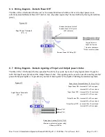
See Section 4.6 for the wiring diagram for the Remote Power Off function
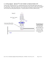
See Section 4.7 for the wiring diagram for the Input / Output Power Status function
Input SPD module
THOR#: TSi040R-150-1P10
(Includes mounting base
and replacement module)
Remote Power Off Relay & Jumper
(See Section 4.6)
2kVA Models
Breaker = 20A
Wiring = #12 AWG
#12 AWG
Green with
Yellow Stripe
Circuit #1 Line
Circuit #2 Line
Circuit #3 Line
Circuit #4 Line
Circuit #5 Line
Circuit #1 Neutral
Circuit #2 Neutral
Circuit #3 Neutral
Circuit #4 Neutral
Circuit #5 Neutral
Neutral Bar
Ground Bar
3kVA Models
Breaker = 30A
Wiring = #10 AWG
Grounding
Electrode
System
#4 AWG
120Vac, 1 Phase, 60hz
(see chart below for
circuit breaker sizing)
Remote Input
Circuit Breaker
Input / Output Power Status
(See Section 4.7)
Figure 4.3


