background image

IO-390-D Series Engine Maintenance Manual


© 2020 Avco Corporation. All Rights Reserved


05-20


March 2020 

Page 19 

IO-390-D Series Engine Maintenance Manual


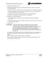
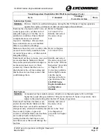
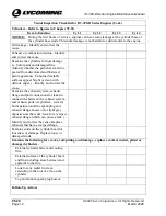
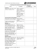
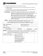
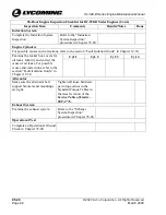
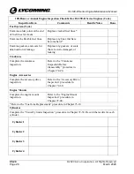
25-Hour Engine Inspection Checklist for IO-390-D Series Engines (Cont.) 

Inspection Item 

Comments 

Results/Notes 

Done 

General 

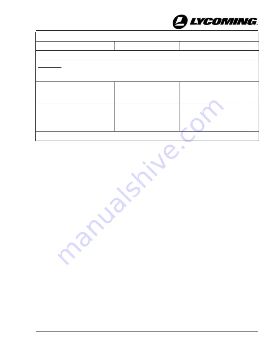
NOTICE:

  If the fuel controls were set to idle 50 to 100 rpm higher than usual on new, rebuilt or 

overhauled engines for the first 25 hours of operation, adjust the fuel controls to the 
usual idle speed between 600 and 700 rpm.


Adjust the fuel controls to the 
usual setting after the first 25 
hours of operation. 

Refer to “Idle Speed and 
Mixture Adjustment” in 
Chapter 72-00. 


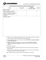
Complete another Operational 
Ground Check in Chapter 72-00. 

Correct any problem before 
flight to make sure the 
engine operates correctly to 
specifications*. 


* Appendix A of the 

IO-390-D Series Engine Installation and Operation Manual.


Содержание IO-390-D Series

Страница 1: ... 2020 Avco Corporation All Rights Reserved Engine Maintenance Manual Principal Manual IO 390 D Series March 2020 Part No MM IO 390 D Series ...

Страница 2: ...rt lycoming com Lycoming s regular business hours are Monday through Friday from 8 00AM through 5 00PM Eastern Time 5 GMT Visit us Online www lycoming com NOTE Lycoming recommends that owners of this manual sign up for email notification on the Technical Publications page of our website https www lycoming com contact knowledge base publications By submitting your email address you will receive not...

Страница 3: ...equired under 43 16 and 91 403 of the Federal Aviation Regulations FAR unless an alternative program has been FAA approved 2 Mandatory Inspection Fuel Injector Lines At every 100 hours of operation and after any maintenance has been done on the engine where the fuel injector lines have been disconnected moved or loosened examine the fuel lines per the Fuel Line Inspection procedure in Chapter 73 1...

Страница 4: ... 390 D Series Engine Maintenance Manual Airworthiness Limitations 2020 Avco Corporation All Rights Reserved Page ii March 2020 IO 390 D Series Engine Maintenance Manual This page intentionally left blank ...

Страница 5: ...ration All Rights Reserved Record of Revisions March 2020 Page iii IO 390 D Series Engine Maintenance Manual RECORD OF REVISIONS Revision Revision Date Revised By Revision Description Original Original Release of Maintenance Manual Part No MM IO 390 D Series ...

Страница 6: ...IO 390 D Series Engine Maintenance Manual Record of Revisions 2020 Avco Corporation All Rights Reserved Page iv March 2020 IO 390 D Series Engine Maintenance Manual This page intentionally left blank ...

Страница 7: ...nge S B 225 03 20 Replacement of Valve Rocker Thrust Washers S B 240 03 20 Mandatory Parts Replacement at Overhaul and During Repair or Maintenance S B 342 03 20 Fuel Line Stainless Steel Tube Assy and Support Clamp Inspection and Installation S B 357 03 20 Engine Inspection After an Engine Has Been Soaked or Immersed S B 369 03 20 Engine Inspection after Overspeed S B 388 03 20 Procedure to Deter...

Страница 8: ...ttention S I 1098 03 20 Propeller Flange Bushing Location S I 1129 03 20 Methods of Checking DC Alternator and Generator Belt Tension S I 1141 03 20 Replacement of Worn Starter Ring Gears S I 1143 03 20 Counterweight Bushing Inspection Replacement and Special Tooling Upgrades S I 1154 03 20 FAA Approved Starters and Alternators S I 1172 03 20 Adjustable Oil Pressure Relief Valve Installation and V...

Страница 9: ...Tappet Body Part Numbers S I 1530 03 20 Engine Inspection in Particulate Laden Environments S I 1535 03 20 Counterweight and Roller Removal Inspection and Installation S I 1566 03 20 Lycoming Engines Approves the Use of Safety Cable S I 1569 03 20 Installation of Lycoming Electronic Ignition System EIS S I 1575 03 20 New Connecting Rod Bushing S L L114 03 20 Reciprocating Engine and Accessory Main...

Страница 10: ...O 390 D Series Engine Maintenance Manual Service Document List 2020 Avco Corporation All Rights Reserved Page viii March 2020 IO 390 D Series Engine Maintenance Manual This page intentionally left blank ...

Страница 11: ...Maintenance 3 Maintenance Practices 3 General Engine Inspection Criteria 5 Requirements for Engine Maintenance 5 Approved Parts 5 Time Limits Service Checks 05 10 Engine Inspection Schedule for IO 390 D Series Engines 7 Required Engine Inspections for IO 390 D Series Engines 05 20 Engine Inspections 9 Visual Inspection for IO 390 D Series Engines 9 Operational Leak Check Sheet for IO 390 D Series ...

Страница 12: ...ston Cleaning 41 Injection Nozzle Cleaning 41 Steel Aluminum or Magnesium Parts Cleaning 42 Spark Plug Cleaning 43 Lead Deposit Removal 43 Volcanic Ash Removal 43 Cleaning Guidelines for a Soaked Engine 44 Cleaning Method for Non Destructive Testing 44 Unscheduled Corrective Maintenance 05 50 Lightning Strike After a Lightning Strike 47 Engine Overspeed 47 Table 1 Overspeed Values for IO 390 D Ser...

Страница 13: ... Oil Servicing Schedule 78 Oil Change Procedure 68 Engine Pre Oil Procedure 69 Oil Suction Screen Removal Inspection Cleaning Installation 71 Oil Pressure Screen Removal Inspection Cleaning Installation 72 Oil Filter Replacement 73 Oil Filter Inspection 73 Identification of Metallic Solids After Oil Servicing 74 Visual Inspection of the Oil Filter Element Oil Pressure Screen and Oil Suction Screen...

Страница 14: ... 72 10 Corrosion Prevention 113 Painting the Engine and Engine Components 113 Table 1 Paint Stripping and Painting Guidelines for Components 113 Limits and Clearances 115 Inspections 115 Engine Assembly Procedure 116 Table 2 Sequence of IO 390 D Series Engine Assembly Procedures 116 Engine Assembly Checklist 122 Propeller Flange Bushing Replacement 72 15 Propeller Flange Bushing Removal 127 Propel...

Страница 15: ...ft Oil Seal Installation 161 Connecting Rod Installation 163 Counterweight Installation 164 Piston Cooling Nozzle Installation if removed 166 Crankshaft Idler Gear Shaft Installation 166 Oil Plug Installation if removed 167 Tappet Assembly Installation 168 Crankshaft Bearing and O Ring Installation 168 Propeller Governor Drive Installation Engines with Front Mounted Propeller Governor Drives 169 C...

Страница 16: ...r Inspection 191 Cylinder Compression Check 192 Table 2 Summary of Cylinder Compression Check Results and Corrective Action 196 Intercylinder Baffle Inspection 197 Cylinder Borescope Inspection 198 Table 3 Borescope Inspection Steps Results and Corrective Action 199 Exhaust Valve and Guide Inspection 199 Cylinder Removal 204 Piston Removal 208 Cylinder Assembly Inspection 209 Piston Inspection 213...

Страница 17: ... Cleaning 234 Oil Cooler Bypass Valve Installation 234 Oil Pressure Screen Housing Removal 235 Oil Pressure Screen Housing Installation 235 Oil Filter Base Removal 235 Oil Filter Base Installation 235 Oil Sump Removal 236 Oil Sump Installation 236 Propeller Governor Oil Line Removal Engines with Rear Mounted Propeller Governor Drives 239 Propeller Governor Oil Line Installation Engines with Rear M...

Страница 18: ...52 Engine Fuel and Control Distribution Maintenance 73 10 Fuel System Inspection 253 Fuel Line Inspection 255 Table 1 Corrective Action for Fuel Lines 258 Fuel Injector Leak Check 259 Fuel System Inspection Checklist 259 Fuel Line Replacement 261 Fuel Injector Replacement 264 Injection Nozzle Replacement 265 Injection Nozzle Fuel Flow Check 267 Fuel Manifold Replacement 267 Fuel Pump Replacement 2...

Страница 19: ...cement 280 EIS Removal 280 EIS Installation 281 Install the Drive Gear Magneto Gear 281 Internally Time the EIS 282 Mount the EIS on the Engine 283 EIS Timing Check 284 Traditional Magnetos Optional 284 Magneto Inspection 284 Magneto to Engine Timing Check 284 Magneto Adjustment Procedure 287 Magneto Replacement Procedure 288 Exhaust System Inspection 78 00 Exhaust System Inspection 291 Appendix A...

Страница 20: ...IO 390 D Series Engine Maintenance Manual Table of Contents 2020 Avco Corporation All Rights Reserved Page xviii March 2020 IO 390 D Series Engine Maintenance Manual This page intentionally left blank ...

Страница 21: ...nic Ignition System F F Fahrenheit FAA Federal Aviation Administration FAR Federal Aviation and Space Regulation ft lb Foot Pound torque FOD Foreign Object Debris FPI Fluorescent Penetrant Inspection G Gal Gallon I ICAs Instructions for Continued Airworthiness ID Inner Inside Diameter in lb Inch Pound torque in Inch inches IOM Engine Installation and Operation Manual K Kg Kilogram kPa Kilopascal L...

Страница 22: ...meter OEM Original Equipment Manufacturer oz Ounce P PID Painted Internal Diameter PMA Parts Manufacturer Approval P N Part Number POH Pilot s Operating Handbook psi Pounds per square inch R rpm Revolutions per Minute S SA Special Advisory SAE Society of Automotive Engineers SB Service Bulletin SI Service Instruction STC Supplemental Type Certificate T TBO Time Between Overhaul TDC Top Dead Center...

Страница 23: ...ropeller flange bushing configurations for these engine models Refer to the latest revision of Service Instruction No SI 1098 for the configuration for your engine model Figure 1 IO 390 D1A6 D3A6 Engine Figure 2 IO 390 D1B6 D3B6 Engine Engine Model Nomenclature The table below identifies the basic nomenclature of the IO 390 engine models Hyphenated numbers and letters in the suffix D1A6 D3A6 D1B6 ...

Страница 24: ...uled servicing procedures airworthiness limitations fault isolation guidelines and procedures to replace components and to disassemble and assemble the engine Refer to the applicable parts catalog to identify spare parts Instructions for Continued Airworthiness This manual the IO 390 D Series Engine Overhaul Manual the latest revision of the Service Table of Limits SSP 1776 and service documents a...

Страница 25: ...annot know all possible hazards or damages it makes a reasonable effort to supply the best known guidance and recommended practices for safe operation and maintenance of its engines The table below defines the four types of safety advisory messages used in this manual as per the American National Standard and ANSI Z535 6 2006 Safety Advisory Conventions Advisory Word Definition DANGER Indicates a ...

Страница 26: ... or other consumables are used in engine service Simplified Technical English The text in the manual is written in the form of Simplified Technical English in compliance with FAA requirements and to make translation into other languages easier Format Chapters in this manual are identified in Air Transport Association ATA format Figures Figures in this manual are for illustration purposes only Figu...

Страница 27: ...ances measurements and torque values B Engine description uncrating procedures acceptance check engine lift procedure engine preservation and storage depreservation engine installation requirements engine installation engine start operation and stop procedures engine initiation break in flight test fuels and oil to be used and operating specifications are included in the IO 390 D Series Engine Ins...

Страница 28: ...d ST 383 Tool Crankshaft Oil Seal Installation ST 389 Tool Crankcase Separating ST 483 Test Plate ST 485 Compressor Piston Ring 64530 Connecting Rod Parallelism and Squareness Gage 64526 2 Block Cylinder 64535 Connecting Rod Bushing Removal Drift 64536 Replacement Drift 64593 Expanding and Staking Tool 0 71 in 18 mm Spark Plug Heli Coil Insert 64597 Connecting Rod Bushing Replacement Block 64594 I...

Страница 29: ...or seal Install a new gasket O ring or seal during component installation where a gasket O ring or seal was removed C If maintenance is done that could cause contamination of the internal components of the engine complete the Oil Change Procedure in Chapter 12 10 D Remove all traces of dirt dust debris and accumulated matter from parts All parts must be clean before they are installed on the engin...

Страница 30: ...on to examine each part for damage or wear and replace the part as needed in accordance with accepted practices and standards to ensure that serviceable parts are installed on the engine G Unless otherwise specified in this manual refer to the latest revision of the Service Table of Limits SSP 1776 for Standard torque values for fittings plugs and hardware fasteners Special torque requirements for...

Страница 31: ...ines must be maintained using Lycoming Engines approved methods and procedures B Refer to the latest revision of Service Bulletin No SB 240 for a list of parts must be replaced whenever they are removed 9 Approved Parts CAUTION LYCOMING DOES NOT GIVE APPROVAL FOR USE OF PARTS MANUFACTURER APPROVAL PMA PARTS ON ITS ENGINES LYCOMING INSTALLATION INSTRUCTIONS DO NOT APPLY TO PMA PARTS EQUIPMENT FAILU...

Страница 32: ...IO 390 D Series Engine Maintenance Manual 05 00 2020 Avco Corporation All Rights Reserved Page 6 March 2020 IO 390 D Series Engine Maintenance Manual This page intentionally left blank ...

Страница 33: ...90 D Series Engines When to Complete Inspection Refer to Chapter 05 20 Before each time interval inspection and during engine servicing or maintenance Visual Inspection Initial 10 hour engine inspection 10 hour Initial Engine Inspection After the first 25 hours of operation or the first 4 months since the engine was placed into service whichever occurs first If one or more new engine cylinders and...

Страница 34: ...IO 390 D Series Engine Maintenance Manual 05 10 2020 Avco Corporation All Rights Reserved Page 8 March 2020 IO 390 D Series Engine Maintenance Manual This page intentionally left blank ...

Страница 35: ...0 hour inspection and every time before you service maintain clean or disassemble the engine WARNING BEFORE ANY ENGINE INSPECTION OR SERVICE PROCEDURE MAKE SURE THE IGNITION SWITCH IS SET TO OFF AND THAT ALL POWER TO THE ENGINE IS DISCONNECTED ENSURE ALL OBJECTS PERSONNEL ARE CLEAR OF THE PROPELLER S ROTATIONAL ARC IF POWER IS ON A LOOSE OR BROKEN WIRE CAN CAUSE THE ENGINE TO START AND THE PROPELL...

Страница 36: ...section Volcanic Ash Removal in Chapter 05 30 Examine all hoses lines connections wiring fittings and baffles for loose connections and any damage Tighten any loose hardware as per the Standard Torque Tables in the latest revision of the Service Table of Limits SSP 1776 Replace field serviceable damaged components Otherwise send the engine to Lycoming Engines for repair Examine the cowling and baf...

Страница 37: ...d secure attachment Make sure that all lines and associated cushion clamps are secure and cannot move or vibrate excessively Ensure that there are no sharp bends in the oil line routing and that no lines are near heat sources that could damage them Identify and correct the cause of any leak Refer to the Oil Line Inspection procedure in Chapter 72 50 Correct any problem before flight to make sure t...

Страница 38: ... Unburned metallic surfaces appear bright or clean with definite edges Identify and correct the cause Examine the exhaust system exhaust flange and port connections for leaks in connections between the exhaust system and exhaust ports of cylinders look for burnt paint around the spark plug and exhaust flange bosses or for light gray deposits near the leaks look for a warped exhaust flange which ca...

Страница 39: ...rdware Refer to Chapter 72 70 Wiring Harness Examine the wiring harness for correct attachment to the electrical connectors and engine Look for broken or frayed wire signs of chafing deterioration abrasion or heat related damage Replace the wiring harness if it is frayed broken chafed abraded or damaged per the aircraft manufacturer s instructions Make sure wiring harness clamps are secure and not...

Страница 40: ...place and not loose Remove any foreign object debris FOD from the engine compartment 5 Start the engine and run up per instructions in the IO 390 D Series Engine Installation and Operation Manual 6 Operate the engine for 3 minutes on the ground per the IO 390 D Series Engine Installation and Operation Manual Complete a leak check while the engine is in operation 7 Shut down the engine 8 Copy and c...

Страница 41: ...achment Make sure that the oil lines are securely attached to prevent vibration Make sure that there are no sharp bends in the oil line routing and that the oil lines are not near heat sources that could damage the oil line Identify and correct the cause of any leak Refer to the Oil Line Inspection procedure in Chapter 72 50 Examine all fuel lines for leaks wear and secure attachment Make sure tha...

Страница 42: ...R SERIOUS INJURY OR A PROPELLER STRIKE NOTICE Copy the blank checklist and complete this checklist as a record of engine maintenance Put the completed checklist in the engine logbook 10 Hour Initial Engine Inspection Checklist for IO 390 D Series Engines Engine Model Number___________________ Engine Serial Number ___________________ Engine Time ___________________________ Date Inspection Done ____...

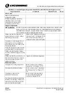
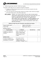
Страница 43: ...AKE SURE THE IGNITION SWITCH IS SET TO OFF AND THAT ALL POWER TO THE ENGINE IS DISCONNECTED ENSURE ALL OBJECTS PERSONNEL ARE CLEAR OF THE PROPELLER S ROTATIONAL ARC IF POWER IS ON A LOOSE OR BROKEN WIRE CAN CAUSE THE ENGINE TO START AND THE PROPELLER TO TURN WHICH CAN LEAD TO DEATH OR SERIOUS INJURY OR A PROPELLER STRIKE 25 Hour Engine Inspection Checklist for IO 390 D Series Engines Engine Model ...

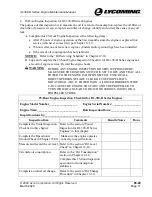
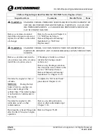
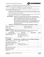
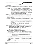
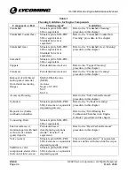
Страница 44: ... OIL SUCTION SCREEN FOR UNWANTED METAL PARTICLES REMOVE ANY CLOGS OR BLOCKAGES IN THE SUCTION SCREEN Remove examine and clean the oil suction screen at the oil sump install the oil suction screen If blockage is found record and identify the blockage metal carbon etc Remove any blockage and clean the oil suction screen Refer to the section Oil Suction Screen Removal Inspection Cleaning Installation...

Страница 45: ...gher than usual on new rebuilt or overhauled engines for the first 25 hours of operation adjust the fuel controls to the usual idle speed between 600 and 700 rpm Adjust the fuel controls to the usual setting after the first 25 hours of operation Refer to Idle Speed and Mixture Adjustment in Chapter 72 00 Complete another Operational Ground Check in Chapter 72 00 Correct any problem before flight t...

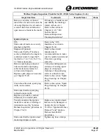
Страница 46: ...__ Engine Serial Number ___________________ Engine Time ___________________________ Date Inspection Done ____________________ Inspection done by ______________________________ Inspection Item Comments Results Notes Done Complete the Visual Inspection Checklist in this chapter Refer to the section Visual Inspection for IO 390 D Series Engines in this chapter Complete the Operational Ground Check in...

Страница 47: ...m as necessary Refer to the aircraft manufacturer s recommendations to make sure the ignition switch and P lead are operating correctly Remove spark plug connector nuts and examine spark plug cable leads and ceramics for corrosion and deposits Replace spark plugs as necessary per Chapter 74 20 Corrosion and deposits are evidence of leaking spark plugs or of improper cleaning of the spark plug wall...

Страница 48: ...e section Fault Isolation Guide in Chapter 12 30 Examine the rocker box covers for oil leaks Identify and correct the cause of oil leaks For possible causes and corrections refer to the section Fault Isolation Guide in Chapter 12 30 Cyl 1 Cyl 2 Cyl 3 Cyl 4 Alternator Make sure the alternator belt support brackets and mountings are tight Tighten all loose hardware per torque values in the Standard ...

Страница 49: ...TED ENSURE ALL OBJECTS PERSONNEL ARE CLEAR OF THE PROPELLER S ROTATIONAL ARC IF POWER IS ON A LOOSE OR BROKEN WIRE CAN CAUSE THE ENGINE TO START AND THE PROPELLER TO TURN WHICH CAN LEAD TO DEATH OR SERIOUS INJURY OR A PROPELLER STRIKE 100 Hour or Annual Engine Inspection Checklist for IO 390 D Series Engines Engine Model Number___________________ Engine Serial Number ___________________ Engine Tim...

Страница 50: ...Magneto to Engine Timing Check in Chapter 74 30 The correct advance timing is stamped on the engine data plate Complete a visual inspection of the magneto wiring conditions and connections vent holes and P lead attachment Clean the magneto vents to make sure that there is no obstruction Make sure the magneto clamps securely attach the magneto to the engine Make sure that the switch wire on the ret...

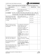
Страница 51: ...ion in Chapter 73 10 Fuel Line 1 Fuel Line 2 Fuel Line 3 Fuel Line 4 Make sure fuel lines are held securely in place using clamps with cushions If no clamps are attached to the fuel line that was in service replace the fuel line per instructions in Chapter 73 10 If cushions on clamps are deteriorated or missing replace the clamps If the clamps are loose replace the fuel line NOTICE Plastic tie str...

Страница 52: ... for deterioration or leakage Replace any gaskets or seals that are worn damaged or leaking Crankcase Complete the crankcase inspection Refer to the Crankcase Inspection Before disassembly procedure in Chapter 72 20 Engine Accessories Complete the accessory drive inspection Refer to the Accessory Drive Inspection procedure in Chapter 72 60 Engine Mounts Complete the engine mount inspection Refer t...

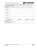
Страница 53: ... or Annual Engine Inspection Checklist for IO 390 D Series Engines Cont Cylinder Compression Check Complete the Cylinder Compression Check Procedure in Chapter 72 30 Record the results for each cylinder Cylinder 1 Cylinder 2 Cylinder 3 Cylinder 4 Inspection Item Comments Results Notes Done Operational Test Complete an Operational Ground Check in Chapter 72 00 ...

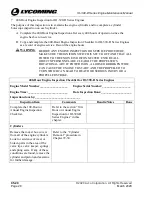
Страница 54: ...LLER S ROTATIONAL ARC IF POWER IS ON A LOOSE OR BROKEN WIRE CAN CAUSE THE ENGINE TO START AND THE PROPELLER TO TURN WHICH CAN LEAD TO DEATH OR SERIOUS INJURY OR A PROPELLER STRIKE 400 Hour Engine Inspection Checklist for IO 390 D Series Engines Engine Model Number___________________ Engine Serial Number ___________________ Engine Time ___________________________ Date Inspection Done ______________...

Страница 55: ...l 400 Hour Engine Inspection Checklist for IO 390 D Series Engines Cont Complete the Cylinder Borescope Inspection procedure in Chapter 72 30 Record the results below for each engine cylinder Cylinder 1 Cylinder 2 Cylinder 3 Cylinder 4 Inspection Item Comments Results Notes Done Operational Test Complete an Operational Ground Check in Chapter 72 00 ...

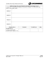
Страница 56: ...E ALL OBJECTS PERSONNEL ARE CLEAR OF THE PROPELLER S ROTATIONAL ARC IF POWER IS ON A LOOSE OR BROKEN WIRE CAN CAUSE THE ENGINE TO START AND THE PROPELLER TO TURN WHICH CAN LEAD TO DEATH OR SERIOUS INJURY OR A PROPELLER STRIKE 500 Hour Engine Inspection Checklist for IO 390 D Series Engines Engine Model Number___________________ Engine Serial Number ___________________ Engine Time _________________...

Страница 57: ...e hours WARNING BEFORE ANY ENGINE INSPECTION OR SERVICE PROCEDURE MAKE SURE THE IGNITION SWITCH IS SET TO OFF AND THAT ALL POWER TO THE ENGINE IS DISCONNECTED ENSURE ALL OBJECTS PERSONNEL ARE CLEAR OF THE PROPELLER S ROTATIONAL ARC IF POWER IS ON A LOOSE OR BROKEN WIRE CAN CAUSE THE ENGINE TO START AND THE PROPELLER TO TURN WHICH CAN LEAD TO DEATH OR SERIOUS INJURY OR A PROPELLER STRIKE 1000 Hour ...

Страница 58: ...IO 390 D Series Engine Maintenance Manual 05 20 2020 Avco Corporation All Rights Reserved Page 32 March 2020 IO 390 D Series Engine Maintenance Manual This page intentionally left blank ...

Страница 59: ...OF THE METAL WHICH CAN CAUSE OIL FOAMING WHEN THE PART IS PUT BACK INTO SERVICE OBEY STANDARD SAFETY PRACTICES REGARDING THE HANDLING OF CLEANING MATERIALS AND THE USE OF PERSONAL PROTECTIVE EQUIPMENT NOTICE IO 390 D Series engines can be equipped with aluminum or magnesium oil sump or accessory housing Be aware of the type of components installed on your engine before cleaning completing maintena...

Страница 60: ...eaning procedure in this chapter Removal of silk thread and or gasket material from crankcase mating flanges Methyl Ethyl Ketone MEK Acetone Napsco SC 200 M 17 M 114 Accessory Housing Refer to the Soft Carbon Removal procedure in this chapter Cylinders Mineral spirits MIL PRF 680 kerosene or equivalent degreasing solvent Refer to the Cylinder Cleaning procedure in this chapter Deposits in cylinder...

Страница 61: ...edure in this chapter Oil sump Oil pump and oil pump housing Mineral spirits MIL PRF 680 or equivalent Oil pressure screen Oil suction screen Mineral spirits MIL PRF 680 or equivalent degreasing solvent Refer to Chapter 12 10 for additional details Oil cooler bypass valve Mineral spirits MIL PRF 680 or equivalent degreasing solvent CAUTION DO NOT USE RAGS OR ANY LINT CLOTH TO CLEAN THIS VALVE Soak...

Страница 62: ... instructions Hartzell Engine Technologies HET formerly Kelly Aerospace starter Refer to starter manufacturer s cleaning instructions All other parts Parts washer solvent using Whirlwash L or equivilant Volcanic ash on engine Refer to the Volcanic Ash Removal procedure in this chapter Refer to the manufacturer s instructions for usage safety data and disposal of all cleaning agents 2 Crankshaft Cl...

Страница 63: ...WITH A NEW CRANKSHAFT 2 Install the tap into the recessed counterbore on the crankshaft 3 Turn the tap as necessary to clean the threads 4 Remove the tap 5 Flush the crankshaft counterbore and alignment dowel pin with mineral spirits MIL PRF 680 or equivalent or Stoddard Solvent or equivalent solvent to remove any debris 6 Dry the crankshaft counterbore threads with compressed air 7 Examine the th...

Страница 64: ... Procedure in this chapter Make sure there is no dirt debris sludge paint or any other substance that could prevent reliable fluorescent penetrant inspection FPI or subsequent oil flow B Remove all plugs from oil passages in the crankcase NOTICE Clean the crankcase after all grit blasting is complete C Use a stiff bristle fiber not wire brush and clean petroleum solvent to clean and flush the oil ...

Страница 65: ...asted Operate the grit blast gun as per the manufacturer s instructions 3 Unless otherwise specified in the manufacturer s instructions use approximately 35 to 45 psi 241 to 310 kPa of air pressure during grit blasting 4 Use compressed air and the vacuum cleaner to remove any debris and residue 5 After all cleaning is complete a Rinse the part in a petroleum solvent b Dry the part with an air blas...

Страница 66: ...e a non wire bristle brush wooden plastic or phenolic scraper or grit blasting per the section Grit Blasting in this chapter to physically remove the hard carbon E Remove any remaining hard carbon from the component with a lint free wipe F Apply a spray coating of preservative oil on the component to prevent corrosion G If the component is not to be installed immediately put the component in a sea...

Страница 67: ...STON RING GROOVES AND ROUND OFF THE OUTER CORNER OF THE PISTON RING LANDS WHICH AFFECTS THE PISTON CONFIGURATION A Remove all oil or preservative oil accumulation from the piston by a soak or wash in a clean bath of mineral spirits Safety Solvent or equivalent degreasing solvent in compliance with MIL PRF 680 specifications B Remove any remaining deposits with a wooden scraper C Gently clean the p...

Страница 68: ...e the nozzles with clean hot water and blow dry with compressed air MEK 1 Soak the nozzles in MEK for one hour 2 Rinse the nozzles with clean hot water and blow dry with compressed air Acetone 1 Soak the nozzles in acetone for one hour 2 Rinse the nozzles with clean hot water and blow dry with compressed air B Install the injection nozzle per Injection Nozzle Installation procedure in Chapter 73 1...

Страница 69: ...spark plug manufacturer s instructions D Wipe the spark plug lead connector clean using a lint free cloth moistened with Methyl Ethyl Ketone MEK acetone wood alcohol naptha or equivalent E Remove all cleaning residue from the spark plug lead connector F Install the spark plug as per the Spark Plug Installation procedure in Chapter 74 20 15 Lead Deposit Removal A Refer to the sections Grit Blast Me...

Страница 70: ...do not use hot acidic cleaning agents or electrolytic cleaning methods such as cathodic cleaning since they can cause hydrogen embrittlement This embrittlement can cause a metallic part to weaken and fail C Additionally acids can generally attack the metals and cause pitting or other corrosion damage D Be sure to remove all cleaning agents E Rinse the part thoroughly F Dry the part G There must no...

Страница 71: ...g Aqueous based cleaning Mechanical cleaning such as grit blasting NOTICE Grit blasting without etching can be an acceptable cleaning method if it can be demonstrated that a sufficiently fine abrasive 150 grit or finer will not cause peening and can be removed by a detergent or alkaline cleaner Etching of the area s to be examined is to be done prior to inspection when evidence exists that previou...

Страница 72: ...IO 390 D Series Engine Maintenance Manual 05 30 2020 Avco Corporation All Rights Reserved Page 46 March 2020 IO 390 D Series Engine Maintenance Manual This page intentionally left blank ...

Страница 73: ... 72 05 and 05 30 2 Complete an inspection of the engine and its components per chapters in this manual and the latest revision of Service Bulletin No SB 401 NOTICE If the EIS does not function correctly or has visible indications of damage replace the EIS 3 Examine the engine compartment in the aircraft the engine external surfaces internal parts for discoloration cracks and other indications of a...

Страница 74: ...b Complete the Cylinder Overspeed Inspection procedure in this chapter c Refer to Chapter 12 10 1 Drain the lubricating system 2 Remove the suction screen and oil filter 3 Examine the suction screen and oil filter element for metal contamination If any unexplained metal accumulation is found identify and correct the cause before putting the engine back into service d Complete the Valve Train Overs...

Страница 75: ...st revision of SI No 1140 6 Valve Train Overspeed Inspection a Either repeated moments or short periods of operation in the overspeed region increase the rate of wear at an accelerated rate in the parts that make up the valve train and consequently decrease engine reliability In addition to the checks completed on the engine during a 100 hour maintenance inspection complete the following steps to ...

Страница 76: ...hange the octane rating from the specifications in Appendix A in the IO 390 D Series Engine Installation and Operation Manual or the latest revision of Service Instruction No SI 1070 could be harmful to the engine 4 Because of many variables it is impossible to be sure of the airworthiness of an engine that has been operated with incorrect fuel except by detailed inspection of the engine by qualif...

Страница 77: ...the engine be sent to Lycoming Engines for evaluation Include a description of the liquid in which the engine was soaked OR NOTICE The following inspection only applies to an engine soaked in water If the engine is soaked in a substance other than water contact Lycoming Engines technical support at the phone number listed in the front of this manual Complete the following in the field in accordanc...

Страница 78: ...rocedure per Chapter 12 10 12 Complete an Operational Ground Check per Chapter 72 00 to make sure the engine is operating correctly before returning the engine to service 13 If visible damage is evident or if engine fails magneto drop off check in accordance with the IO 390 D Series Engine Installation and Operation Manual replace the EIS with a new unit E Engine on Fire or Near a Fire Replace any...

Страница 79: ...er to Chapter 72 20 to remove and examine the connecting rods c If all connecting rods are in compliance with the specified criteria in the latest revision of the Service Table of Limits SSP 1776 install the connecting rods d If any connecting rod is not in compliance with acceptance criteria disassemble the engine to examine the crankcase and crankshaft as per Chapters 72 05 and 72 20 G Volcanic ...

Страница 80: ...air filter as per the aircraft manufacturer s instructions to remove any internal contamination that can cause premature wear because of the highly abrasive effects from most solid particles Replace the intake air filter as a precaution to be sure there are no effects from particulate contamination Replace the intake air filter again after the next flight Examine the external condition of the engi...

Страница 81: ...ve sticking is a problem refer to the latest revisions of Service Letter No L197 and Service Instruction No SI 1425 and complete the 1000 hour inspection in Chapter 05 20 Refer to the section Corrective Action for Valve Sticking in Chapter 72 30 If the 1000 hour inspection is completed before 1000 hours of operation because of valve sticking complete the scheduled 1000 hour inspection after the ne...

Страница 82: ...nections for leaks Tighten any loose connections per the torque values in the latest revision of the Service Table of Limits SSP 1776 and look for leaks Replace leaking oil hoses per Chapter 72 50 d Per Chapter 12 10 complete the Oil Suction Screen Removal Inspection Cleaning Installation at the oil sump and the Oil Filter Inspection Look for blockage or metal deposits If metal or blockage is foun...

Страница 83: ...T CRANKSHAFT PROPELLER FLANGES TO RESTORE MAXIMUM RUN OUT SPECIFICATION AS NOTED IN THE LATEST REVISION OF THE SERVICE TABLE OF LIMITS SSP 1776 IF THE CRANKSHAFT PROPELLER FLANGE IS BENT REPLACE THE CRANKSHAFT DO NOT TRY TO STRAIGHTEN OR GRIND THE CRANKSHAFT PROPELLER FLANGE REFER TO THE LATEST REVISION OF SERVICE BULLETIN NO 201 DAMAGE TO A PROPELLER IS SERIOUS AND CAN CAUSE THE ENGINE TO BE UNAI...

Страница 84: ...CASE P N MATCH NO 4 Disassemble the engine remove the crankshaft camshaft connecting rods crankshaft gear and internal steel parts Refer to Table 1 Sequence of Engine Disassembly in Chapter 72 05 5 Complete grit blast cleaning of the crankcase with fine abrasive 150 grit or finer remove all coatings on the crankcase and engine mount bosses Make sure there is no dirt debris sludge paint or any othe...

Страница 85: ...re and checklist in Chapter 72 20 11 Examine the crankshaft counter bored recess the alignment dowel especially at the base where it goes into the crankshaft the bolt hole threads and the crankshaft gear for wear galling corrosion and fretting Refer to the latest revision of Service Bulletin No 475 If the bolt hole threads are damaged they cannot be repaired Replace the crankshaft 12 Clean the cra...

Страница 86: ...t Flange run out within acceptable limits use crankshaft Replace crankshaft 15 Measure the main bearing run out on the crankshaft Refer to the latest revision of Part I of the Service Table of Limits SSP 1776 for the main bearing run out tolerance Record the main bearing run out measurement Main bearing run out within acceptable limits use crankshaft Replace crankshaft 16 Measure the polished dime...

Страница 87: ...SP 1776 Reference 504 Squareness Measurement Connecting Rod 1 Connecting Rod 2 Connecting Rod 3 Connecting Rod 4 NOTICE The magnetic particle inspection must be done by a certified technician as per the latest revision of Service Instruction No 1285 20 Complete a magnetic particle inspection on the crankshaft Record test results Magnetic particle test results acceptable Replace crankshaft 21 Compl...

Страница 88: ...d FPI on the oil sump Record test results Use oil sump Replace oil sump 28 Complete the visual inspection and FPI on the engine mounts Record test results Use engine mounts Replace engine mounts 29 Complete the visual inspection and FPI on the accessory housing Record test results Use accessory housing Replace accessory housing 30 Complete the visual inspection and FPI on the oil pump impeller Rec...

Страница 89: ...ght rollers and bushings Refer to Chapter 72 20 in this manual 37 Review the documents of all engine mounted accessories including the propeller governor if installed etc for continued airworthiness instruction 38 Assemble and install the engine Install the propeller and test the engine Complete an Operational Ground Check of the engine In accordance with instructions in Chapters 72 00 and 72 10 3...

Страница 90: ...hich can cause indications to be tightly closed and therefore missed during future inspections C Requirements for NDT Personnel Personnel who complete the Magnetic Particle and Fluorescent Penetrant Inspections on Lycoming engine components must be qualified and certified to a written procedure in accordance with NAS 410 Certification and Qualification of NDT personnel Also personnel who make the ...

Страница 91: ...FICIENT OIL LEVEL ENGINE DAMAGE CAN OCCUR REFER TO THE SECTION OIL STARVATION SUDDEN LOSS OF OIL PRESSURE IN CHAPTER 05 50 A The oil in the engine must be kept at the correct level for the engine to operate correctly B Measure the oil level of an engine before every flight as follows 1 Pull out the oil level gage assembly dipstick from the oil level gage tube Figure 1 Figure 1 Oil Fill Tube and Oi...

Страница 92: ...dentified in Appendix A of the IO 390 D Series Engine Installation and Operation Manual B Refer to the latest revision of Service Instruction No SI 1014 for additional details 5 Add Oil to the Engine NOTICE Each time oil is added to the engine record the quantity of oil added in the engine logbook to calculate oil consumption A Oil Additives Refer to the latest revision of Service Instruction No S...

Страница 93: ... and oil filter replacement are shown in Table 1 Table 1 Oil Servicing Schedule Task Frequency Initial oil change and oil filter replacement or oil pressure screen cleaning of any new rebuilt or overhauled engine or engine returned to service after storage After the first 25 hours of operation after initial start up or every 4 months whichever occurs first Repeat as necessary until oil consumption...

Страница 94: ... sump Send the oil sample in the vial to the same laboratory that has been used in the past for spectrographical analysis to compare past results and identify a wear trend pattern Refer to the latest revision of Service Letter No L171 for spectrographic oil analysis CAUTION THE ENGINE OIL WILL BE VERY HOT AND CAN CAUSE BURNS HANDLE WITH CARE A Drain the oil from the oil sump as follows 1 Put a sui...

Страница 95: ...tivity complete the Engine Pre Oil Procedure in this chapter NOTICE If an oil hose has been disconnected or if the oil cooler was drained or replaced or after any prolonged period of engine inactivity complete the Engine Pre Oil Procedure in section 9 of this chapter H Complete the Oil Level Check procedure in this chapter I Safety cable wire the oil sump drain plug suction screen plug and oil fil...

Страница 96: ...evidence of oil pressure of at least 20 psi 138 kPa within 10 to 15 seconds If there is no oil pressure within 10 to 15 seconds stop energizing the starter Wait at least 30 seconds and repeat the pre oil start cycle Up to six consecutive pre oil start cycles can be done Afterwards let the starter cool for 30 minutes If stable oil pressure is not achieved stop pre oiling and contact Lycoming Engine...

Страница 97: ...ll metallic particles or shavings which are acceptable 3 If steel copper or aluminum particles are found on the oil suction screen examine the cylinders and other metal components for wear or damage G Clean the oil suction screen with mineral spirits or equivalent degreasing solvent H Apply Food Grade Anti Seize to the threads of the screen plug and install the oil suction screen do not flare the ...

Страница 98: ...ition of the oil and particles on the oil pressure screen Look for shining metallic residue Refer to the section Engine Wear and Oil Analysis in this chapter NOTICE Results from examination of the oil pressure screen on the first oil change of a new rebuilt or newly overhauled engine usually will show small metallic particles shavings which are acceptable G Clean the oil pressure screen with miner...

Страница 99: ...lter on the oil filter base as shown in Figure 4 G Torque the oil filter to 17 ft lb 23 Nm or per the oil filter manufacturer s instructions H Install new safety wire cable on the oil filter Figure 5 to keep it securely in place per the latest revision of Service Instruction No SI 1566 Figure 5 Safety Wire on Oil Filter 13 Oil Filter Inspection A Cut open the removed oil filter canister with an ap...

Страница 100: ...ontent complete a Visual Cylinder Inspection and or Cylinder Borescope Inspection on each engine cylinder per Chapter 72 30 15 Visual Inspection of the Oil Filter Element Oil Pressure Screen and Oil Suction Screen When metallic particles are found on a filter element or screen a visual inspection of the metallic particles on the filter element or screen is to be done to help identify and narrow th...

Страница 101: ...ation to look at the panels and folds on the filter element for any shiny metallic solids Look for any copper colored metallic particles Look for any copper colored metallic particles Use non metallic tweezers or a pick to sort chunks chips and particles that look different Estimate the size and number of metallic particles Estimate the size and number of metallic particles Typically small metalli...

Страница 102: ...tity and size of the particles Bronze When placed in nitric acid turns bright green Connecting rod bushings Rocker bushings Crankshaft bearings Intake valve guide Piston pin plug Idler gear bushing Refer to Table 3 for the quantity and size of the particles Nickel Not picked up by magnet Exhaust flange V band coupling Gasket Refer to Table 3 for the quantity and size of the particles Stainless ste...

Страница 103: ...and water or a sodium hydroxide solution the aluminum particles bubble and fizz and form a black residue Crankcase Accessory housing Oil pump body Cylinder head Pistons Piston pin plugs Oil sump baffle Turbocharger inlet housing Sleeve bearings Refer to Table 3 for the quantity and size of the particles Magnesium Oil sump Refer to Table 3 for the quantity and size of the particles Tin Soft malleab...

Страница 104: ...l Corrective Action 3 Pieces of metal that are chunks greater than 3 16 in 4 8 mm or chips smaller than chunks NOTICE A mixture of magnetic and nonmagnetic material can indicate valve or ring and piston failure NOTICE Remove the bottom spark plugs to identify a non conforming cylinder Corrective Action 4 1 4 teaspoonful or more of nonmagnetic plating with or without a copper tint could vary in siz...

Страница 105: ... past the oil filter Possibly only one engine cylinder is damaged or spark plug is worn or damaged Corrective Action 5 If the cause of the metal contamination cannot be identified speak with the Lycoming Engines Technical Support phone number at the front of this manual If there is unusual aluminum bronze or iron contamination in the oil make sure you have a full description of the engine model se...

Страница 106: ...ve and examine the oil filter d If the oil filter is clean install a new oil filter e Operate the engine in flight for 10 hours f Remove and examine the oil filter g If either the oil filter is clean resume the routine oil servicing schedule If chunks or more than 45 metallic particles are found ground the aircraft and proceed to Corrective Action 3 3 a Per sections in this chapter complete Oil Ch...

Страница 107: ...ller governor can have a small screen molded within the propeller governor gasket Remove this gasket and look for particle contamination on the propeller gasket screen Replace with a new propeller governor gasket If less than 10 metallic particles are found on this screen If 10 or more metallic particles or flakes or slivers of metal are found on this screen A Replace the propeller governor gasket...

Страница 108: ...IO 390 D Series Engine Maintenance Manual 12 10 2020 Avco Corporation All Rights Reserved Page 82 March 2020 IO 390 D Series Engine Maintenance Manual This page intentionally left blank ...

Страница 109: ...sible causes B The Ref column in Table 1 contains references to the following 1 A numeric entry such as 72 00 refers to a chapter in this manual 2 IOM refers to the IO 390 D Series Engine Installation and Operation Manual 3 AMM refers to the Airframe Manufacturer s Manual 4 POH refer to the Pilot s Operating Handbook Table 1 Fault Isolation Guide Problem Cause Corrective Action Ref Engine will not...

Страница 110: ...d Ignition Harness Removal Ignition Harness Inspection Ignition Harness Installation 74 20 Incorrect EIS to engine timing Refer to the EIS Troubleshooting Guide in this chapter Magneto incorrectly timed to engine Complete the Magneto to Engine Timing Check 74 30 Magneto internal timing not adjusted correctly or E gap drifting because of point or follower wear Replace magneto with a serviceable uni...

Страница 111: ... cylinder will be cold after 2 minutes of engine operation 2 Complete the Injection Nozzle Fuel Flow Check 3 Complete the Injection Nozzle Removal procedure 4 Complete the Injection Nozzle Cleaning procedure 5 Complete the Injection Nozzle Installation procedure 73 10 05 30 73 10 Leak in induction system Complete the Induction System Inspection procedure 72 80 Internal fuel injector leak Complete ...

Страница 112: ...st pump is on Lean idle mixture 1 Enrich the idle mixture as per the section Idle Speed and Mixture Adjustment 2 Readjust the idle speed 72 00 Fuel pressure too low at idle speed engine could also lose fuel pressure as the aircraft climbs 1 Look for loose fuel line fitting Torque any loose fuel line fitting as per the latest revision in the Service Table of Limits SSP 1776 2 Make sure the fuel pum...

Страница 113: ...l flow gage Fuel injector rich Remove the fuel injector Either send it to a manufacturer approved repair facility or replace it as per the Fuel Injector Replacement procedure 73 10 Low fuel flow Dirty fuel pump filter Remove and clean the fuel pump filter with acetone or MEK blow out with compressed air and re install the fuel pump filter or Replace the fuel pump filter AMM Faulty fuel flow gage 1...

Страница 114: ...s instructions 2 Adjust the fuel pressure in accordance with the aircraft manufacturer s instructions 3 Replace the fuel pump or fuel pressure regulator Refer to the Fuel Pump Replacement procedure AMM 73 10 Engine will not turn static rpm or will not develop rated rpm Decreased air flow in the induction system 1 Make sure that the air filters are clean 2 Complete the Induction System Inspection a...

Страница 115: ...g Removal Spark Plug Cleaning Spark Plug Fouling Spark Plug Gap Setting Spark Plug Rotation Spark Plug Installation 74 20 05 30 Incorrect fuel flow 1 Look for blocked fuel lines to the engine 2 Remove the fuel injector inlet screen and flush out with acetone or MEK Blow out with compressed air 3 Disconnect the fuel flow gage and install a master fuel flow gage to make sure the aircraft fuel flow g...

Страница 116: ...e connections or replace manifold gaskets as necessary Engine hesitates misses Fault in the ignition system 1 Visually examine the harness for physical damage 2 Examine leads using a high tension lead tester 3 Replace worn or damaged components as necessary 4 Complete the following procedures Spark Plug Removal Ignition Harness Inspection Spark Plug Inspection Spark Plug Cleaning Spark Plug Gap Se...

Страница 117: ...t main bearing has too much clearance Complete a Propeller Oil Control Leak Test 72 20 Irregular oil pressure Oil pump is sucking air Replace the oil pump per the Oil Pump Removal and Oil Pump Installation procedures 72 25 Low oil pressure Oil not of the correct viscosity for ambient temperature Make sure oil of the correct viscosity for the ambient temperature is used Refer to the latest revision...

Страница 118: ...0 Blockage at inlet side of oil pump Remove and clean the oil suction screen and oil passage on the inlet side of the oil pump Refer to the section Oil Suction Screen Removal Inspection Cleaning Installation 12 10 Damaged oil pressure relief valve seat Replace the oil pressure relief valve seat per the latest revision of Service Instruction No SI 1172 Excess internal oil leakage Look for Loose or ...

Страница 119: ...correctly Test the oil pressure gage AMM Excessive oil consumption New piston rings are not completely seated break in not done As part of break in operate the engine at not less than 65 power for the first 50 hours IOM Piston rings are worn broken or incorrectly installed OR Cylinder barrels are glazed or worn too much 1 Complete the Cylinder Compression Check Procedure 2 Complete the Cylinder Bo...

Страница 120: ...r safety wire or cable and the oil access door closes correctly 2 Make sure that the breather tube is accurately cut and the crankcase ventilation system is installed correctly per the airframe manufacturer s instructions 12 10 Oil level too high Do not fill above the maximum oil sump capacity IOM Appendix A Drain some oil start of Oil Change Procedure 12 10 High oil temperature Cooling baffles ar...

Страница 121: ...1 Install the master temperature gage and operate the engine to compare gages 2 Replace the faulty gage if necessary AMM Higher than normal cylinder head temperatures Incorrect EIS to engine timing Refer to the EIS Troubleshooting Guide in this chapter High manifold pressure at idle Air leak in induction system Examine the induction system for leaks Identify and correct the cause of all leaks NOTI...

Страница 122: ...mmended viscosity of oil for the ambient temperature per the latest revision of Service Instruction No SI 1014 Oil passage is blocked from the pressure relief valve to the sump 1 Remove the pressure relief valve from the engine 2 Push a soft copper wire through the oil passage to the oil sump to remove blockage NOTICE If blockage continues remove the oil sump and clean the passage 72 50 Sluggish p...

Страница 123: ...timed to engine 1 cylinder TDC Ignition not timed to engine correctly Reinstall ignition unit in accordance with installation instructions Unable to time ignition to engine 1 cylinder verified TDC LED timing light on solid but unable to find the point when the LED goes off TDC marker point 4 cylinder engine Timing gear installed upside down on ignition unit Remove timing gear from ignition unit ro...

Страница 124: ...ed to engine 1 cylinder TDC Verify all spark plugs are firing using CHT Verify ignition unit is configured correctly to engine base timing Ignition harness wires connected to incorrect spark plugs Check routing of harness wires Internal ignition fault Contact Lycoming customer support Ignition unit is not configured correctly to engine base timing Ignition unit not configured correctly to engine b...

Страница 125: ...er terminal P lead terminal grounded P lead wire is connected to ground Check ignition switch Check integrity of p lead wire for chaffing to ground Internal ignition fault if p lead terminal is grounded with wire removed Contact Lycoming customer support P lead terminal not grounded open Ignition verified as correctly timed to engine 1 cylinder TDC Ignition harness wires connected to incorrect spa...

Страница 126: ...IO 390 D Series Engine Maintenance Manual 12 30 2020 Avco Corporation All Rights Reserved Page 100 March 2020 IO 390 D Series Engine Maintenance Manual This page intentionally left blank ...

Страница 127: ...tions 8 Drain oil from engine Refer to the Oil Change Procedure in Chapter 12 10 9 Remove accessories 10 If the engine is to be stored complete the engine preservation procedure before engine removal Refer to instructions in the IO 390 D Series Engine Installation and Operation Manual 2 Engine Removal Procedure A Complete the prerequisites in the section Engine Removal Prerequisites in this chapte...

Страница 128: ...raft fuel supply lines in accordance with the aircraft manufacturer s instructions J Refer to the aircraft manufacturer s instructions to disconnect any accessory connection or to remove any external accessories to enable removal of the engine from the aircraft K Make sure that all wires lines and attachments between the engine and airframe are disconnected and capped L Reinstall the spark plug in...

Страница 129: ...rviced Engine for Installation New gaskets seals O rings and packing Make sure the new parts are not brittle torn cut or cracked and do not have flashings deterioration wear or deformities Always install new gaskets seals O rings or packing New safety wire cable lock nuts lock washers tab washers and cotter pins New replacement part for any part that had to be discarded Oil per specifications in A...

Страница 130: ...n Manual NOTICE Engine initiation procedures are to be done in the field on any of the following newly installed Lycoming engines Any new overhauled or rebuilt engine from the factory and field overhauled engines Engine taken out of storage if not run in when put in storage An engine which has been disassembled re assembled 5 Idle Speed and Mixture Adjustment NOTICE The fuel injector servo has a s...

Страница 131: ...re adjustment wheel to adjust the idle speed mixture C After the adjustment run up the engine again to 2000 rpm Complete the previous steps until the idle speed check shows a momentary increase of approximately 25 to 50 rpm D Make the final idle speed adjustment for the desired idling rpm with a closed throttle E If the idle speed setting is not stable after repeated attempts complete a check of t...

Страница 132: ...ntenance Manual 7 Return to Service Procedure Before returning this engine to service Make sure that you correct all problems and complete all of the necessary maintenance Complete the Operational Ground Check in this chapter Specifically monitor o Power output static and idle rpm o Fuel and oil pressure o Cylinder and oil temperatures ...

Страница 133: ...ence Step Reference Step 1 Spark Plug Removal procedure in Chapter 74 20 Step 3 EIS Removal or Magneto Removal procedure in Chapter 74 30 Figure 3 EIS Magnetos Remove the spark plugs Figure 1 Remove the two Lycoming Electronic Ignition Modules or magnetos Figure 3 Figure 1 Spark Plugs Step 2 Remove the ignition harness and ignition leads Figure 2 Ignition Harness Removal procedure in Chapter 74 20...

Страница 134: ...ter 73 10 Fuel Line Removal Fuel Injector Removal Injection Nozzle Removal Fuel Manifold Removal Fuel Pump Removal Figure 8 Fuel Lines and Fuel Components Remove the alternator alternator bracket and alternator belt Figure 5 Step 6 Remove the starter Figure 6 Starter Removal procedure in Chapter 72 70 Figure 6 Starter Step 9 Remove the intake pipes Figure 9 Intake Pipe Removal procedure in Chapter...

Страница 135: ...emove the propeller governor oil line Engine with rear mounted propeller governor Figure 12 Propeller Governor Oil Line Removal procedure in Chapter 72 50 Step 15 Remove both crankshaft idler gears Figure 15 Crankshaft Idler Gear and Bushing Removal procedure in Chapter 72 20 Figure 15 Crankshaft Idler Gears Figure 12 Propeller Governor Oil Line Step 13 Remove any airframe components from the acce...

Страница 136: ...cylinder baffles Figure 17 Remove the pistons Figure 20 Step 18 Chapter 72 30 in this manual Figure 18 Rockers Shroud Tubes and Push Rods Step 21 Connecting Rod Removal in Chapter 72 20 Figure 20 Connecting Rod Remove the rocker covers valve rockers rocker shafts push rods and shroud tubes Figure 18 Remove the connecting rods Figure 21 Step 19 Cylinder Removal procedure in Chapter 72 30 Figure 19 ...

Страница 137: ...idler gear shafts Figure 27 Crankshaft Idler Gear Shaft Removal procedure in Chapter 72 20 Step 24 Remove the tappets main bearings and O rings Figure 24 Tappet Main Bearing and O Ring Removal in Chapter 72 20 Figure 23 Tappets Main Bearings and O Rings Figure 26 Crankshaft Idler Gear Shafts Step 30 Remove the piston cooling nozzles Figure 30 Piston Cooling Nozzle Removal in Chapter 72 20 Step 25 ...

Страница 138: ...IO 390 D Series Engine Maintenance Manual 72 05 2020 Avco Corporation All Rights Reserved Page 112 March 2020 IO 390 D Series Engine Maintenance Manual This page intentionally left blank ...

Страница 139: ...mponent Do not get paint on any mating surfaces or under the cylinder hold down nuts There must be metal to metal contact to ensure correct torque Mask mating surfaces and the area where the nut will contact the component surface Table 1 includes paint stripping and painting guidelines for components All paint is to be sprayed however if it is necessary to use a brush use care to prevent an accumu...

Страница 140: ...rom the cylinder Paint strippers are usually organic solvents like MEK or acetone or toluene etc and typically will not cause any damage to metals A vapor degreaser is best suited for this purpose NOTICE Masking tape corks plugs metal covers etc are acceptable for masking purposes 2 Mask off the following parts of the cylinder Rocker box section including the rocker box flange Both valve ports and...

Страница 141: ... logbook A Bearing Surface Inspection 1 Examine all bearing surfaces for scoring galling and wear If a part has one of the defects discard it and replace it with a new one 2 Make sure that the clearance of each bearing agrees with the specification in the latest revision of the Service Table of Limits SSP 1776 If a bearing is not in the specified limits in the latest revision of the Service Table ...

Страница 142: ...tallation procedure in Chapter 72 20 Figure 1 Crankshaft Gear Figure 4 Connecting Rods Step 6 Counterweight Installation procedure in Chapter 72 20 Figure 5 Counterweights Step 3 Install the expansion plug on the crankshaft Figure 2 Expansion Plug Installation procedure in Chapter 72 20 Figure 2 Expansion Plug Install the counter weights on the crankshaft Figure 5 Step 4 Start install ation of the...

Страница 143: ... 6 Crankshaft Idler Gear Shafts Figure 9 Tappets and Oil Seal Rings Step 8 Install the oil plugs if removed Figure 7 Oil Plug Installation procedure in Chapter 72 20 Step 11 Install the main bearings bolts and O rings in the crankcase Figure 10 Crankshaft Bearing and O Ring Installation procedure in Chapter 72 20 Figure 7 Oil Plugs Figure 10 Main Bearings and O Rings Step 9 Oil Pressure Relief Val...

Страница 144: ...ankshaft oil seal in the crankcase Figure 15 Figure 12 Camshaft Figure 15 Split Oil Seal and Solid Ring Oil Seal Step 14 Crankshaft Installation procedure in Chapter 72 20 Step 17 Crankshaft Idler Gear Installation procedure in Chapter 72 20 Install the crankshaft in the crankcase Figure 13 Install the crankshaft idler gears Figure 16 Figure 13 Crankshaft Figure 16 Crankshaft Idler Gears Step 15 A...

Страница 145: ...rs on the crankcase Figure 21 Cylinder Installation section in Chapter 72 30 Figure 18 Accessory Housing Figure 21 Engine Cylinders Step 20 Install the oil sump on the crankcase Figure 19 Oil Sump Installation in Chapter 72 50 Figure 19 Oil Sump Step 23 Install the starter ring gear support on the engine Figure 22 Starter Ring Gear Support Installation procedure in Chapter 72 70 Figure 22 Starter ...

Страница 146: ...m of each engine cylinder Figure 27 Figure 24 Oil Level Gage Tube Figure 27 Spark Plugs Step 26 Intercylinder Baffle Installation procedure in Chapter 72 30 Step 29 Install the Lycoming Electronic Ignition System modules or magnetos on the engine Figure 28 EIS Installation or Magneto Installation procedure in Chapter 74 30 Install inter cylinder baffles Figure 25 Figure 25 Intercylinder Baffle Fig...

Страница 147: ...ion procedure in Chapter 73 10 Figure 31 Fuel Manifold Step 36 Install the starter Figure 35 Starter Installation procedure in Chapter 72 70 Figure 35 Starter Step 33 Install the fuel injectors Figure 32 Fuel Injector Installation procedure in Chapter 73 10 Figure 32 Fuel Injector Step 37 Install the alternator bracket and belt Figure 36 Alternator and Bracket Installation and Alternator Belt Inst...

Страница 148: ... in Chapter 72 20 CAUTION FOR CORRECT ENGINE OPERATION THE CRANKSHAFT GEAR MUST BE INSTALLED CORRECTLY WITH NO GAP IN THE MATING SURFACES BETWEEN COUNTERBORED END OF THE CRANKSHAFT AND THE CRANKSHAFT GEAR Complete the Crankshaft Gear Installation with a new crankshaft gear bolt and new lockplate Chapter 72 20 Install a new expansion plug in the crankshaft per the Expansion Plug Installation proced...

Страница 149: ...ts installed in the engine logbook Complete the Crankshaft Bearing and O Ring Installation procedure in Chapter 72 20 Complete the Propeller Governor Drive Installation procedure in Chapter 72 20 NOTICE If a new or reconditioned camshaft is to be installed install new tappet bodies Refer to the Camshaft Replacement Guidelines section in the latest revision of Service Instruction No SI 1011 for gui...

Страница 150: ...the crankcase halves per the Crankcase Assembly procedure and follow the torque sequence in Chapter 72 20 Complete the Crankshaft Oil Seal Installation procedure in Chapter 72 20 Complete the Crankshaft Idler Gear Installation procedure in Chapter 72 20 Complete the Crankshaft Endplay Clearance Check in Chapter 72 20 after the crankcase is assembled Complete the Fuel Pump Plunger Inspection in Cha...

Страница 151: ...er the Starter Ring Gear Support Installation procedure in Chapter 72 70 Complete the Oil Level Gage Tube and Assembly Installation procedure in Chapter 72 50 Complete the Intercylinder Baffle Installation procedure in Chapter 72 30 Install a new oil drain tube at each cylinder head and at the crankcase per the Oil Drain Tube Installation procedure in Chapter 72 30 Complete the Intake Pipe Install...

Страница 152: ...tarter Installation procedure in Chapter 72 70 Complete the Alternator and Bracket Installation and Alternator Belt Installation procedures in Chapter 72 70 Install the engine in the airframe per instructions in the IO 390 D Series Engine Installation and Operation Manual and applicable Airframe Maintenance Manual Complete the Add Oil to the Engine procedure in Chapter 12 10 Complete an Operationa...

Страница 153: ... for the latest part number and propeller flange bushing location since an update of Service Instruction No 1098 is more likely to occur before the parts catalog update C Use the Propeller Flange Bushing Removal Installation Tool ST 115 to remove each bushing from the propeller flange 2 Propeller Flange Bushing Installation CAUTION IF THE PROPELLER FLANGE BUSHING OF THE CORRECT PART NUMBER IS NOT ...

Страница 154: ...IO 390 D Series Engine Maintenance Manual 72 15 2020 Avco Corporation All Rights Reserved Page 128 March 2020 IO 390 D Series Engine Maintenance Manual This page intentionally left blank ...

Страница 155: ...or out of roundness is found replace the breather tube NOTICE In the next step do not use a torque tool during the check for loose crankcase thru bolts F Manually turn by hand each crankcase thru bolt as a check for loose bolts If the bolt can be manually turned remove the bolt and examine the bolt for stripped threads If the bolt threads are intact install and torque the bolt in accordance with t...

Страница 156: ...ES C Use a slide hammer a Crankcase Thru Stud Puller ST 271 or Crankcase Thru Stud Driver ST 317 or a plastic hammer to remove the four thru studs from the crankcase Figure 3 D Remove the remaining bolts and nuts that attach the crankcase halves E Insert one used pushrod into each of the four holes where the thru studs were removed to support the camshaft and crankshaft when the crankcase halves a...

Страница 157: ...ront of the flange as a suffix to the part number In addition to the code symbols the letters RN are stamped as a suffix to the crankshaft serial number indicating that the crankshaft has been renitrided Figure 9 Crankshaft in V Block Type Fixture K Tappet Main Bearing and O Ring Removal 1 Remove the hydraulic tappet plungers using the Tappet Assembly Tool P N 64941 CAUTION IF A TAPPET ASSEMBLY TO...

Страница 158: ...nd a right angle in one end of a piece of wire and insert this end into the space between the plunger assembly and the tappet body Turn the wire 90º to engage a coil of the spring and draw out the hydraulic tappet plunger assembly Refer to Figure 11 Figure 10 Removing Push Rod Socket Figure 11 Removing Hydraulic Tappet Plunger Assembly 5 Remove and discard the crankshaft bearings crankshaft front ...

Страница 159: ...rnor gasket 3 Cut and remove the safety wire cable from the idler gear shaft plug Figure 13 4 Remove the idler gear shaft plug and gasket from the crankcase Figure 13 Discard the gasket Figure 13 Propeller Governor Drive 5 Remove and discard the set screw from the propeller governor idler gear shaft If the set screw was peened or staked in the hole remove any debris 6 Support the propeller governo...

Страница 160: ... Housing Figure 15 Oil Plugs in the Oil Sump Figure 16 Oil Plugs in the Crankcase N Crankshaft Idler Gear Shaft Removal 1 Remove the safety wire Figure 17 from the nut and three bolts that attach the crankshaft idler gear shafts to the crankcase halves 2 Remove the nut and three bolts Figure 18 that attach the crankshaft idler gear shafts to the crankcase halves 3 Remove the two idler gear shafts ...

Страница 161: ...USE CRANKSHAFT FAILURE A Bend the tabs of the crankshaft gear bolt lockplate down flat against the crankshaft gear B Remove the crankshaft gear bolt lockplate and crankshaft gear from the crankshaft Figure 20 Discard the bolt and the lockplate NOTICE Any time the crankshaft gear bolt Figure 20 is removed from the crankshaft discard this bolt and replace it with a new bolt during assembly Do not re...

Страница 162: ...plug remnants Discard the expansion plug and inner plug Figure 21 Crankshaft and Counterweight Assembly CAUTION WHEN TOUCHING COUNTERWEIGHTS AND ROLLERS DO NOT MAKE SCORES SCRATCHES OR ETCH MARKINGS OF ANY KIND ON THE CRANKSHAFT AND ROLLERS A MARK IN ANY OF THESE AREAS CAN CAUSE THE PART TO WEAKEN AND POSSIBLY FAIL NOTICE Counterweights Figure 22 of a specific order are installed in specified loca...

Страница 163: ...condition Figure 22 Counterweight Rollers Counterweight Bushings and Lug Bushings CAUTION COUNTERWEIGHT BUSHINGS MUST ALWAYS BE REPLACED WITH NEW COUNTERWEIGHT BUSHINGS WHENEVER THESE BUSHINGS ARE REMOVED DAMAGE OR WEAR ON THE CRANKSHAFT COUNTERWEIGHT BUSHINGS COULD CAUSE FAILURE OF THE COUNTERWEIGHT AND OR THE CRANKSHAFT NOTICE All counterweight bushings on all of the counterweights must be repla...

Страница 164: ... within allowable limits Complete the crankcase dimensional inspection as follows A Install new crankshaft bearings at all main bearing locations in the crankcase halves Figure 12 B Assemble the crankcase halves and install thru studs Figure 3 C Use washers and nuts on the thru studs to install the Torque Hold Down Plates ST 222 Figure 83 at the cylinder pads over the thru studs Tighten the nuts o...

Страница 165: ...nt main bearing measurement _________ inches Crankshaft at center main bearing measurement _________ inches Crankshaft at rear main bearing measurement _________ inches Measure the I D of the camshaft bearing saddles formed by the crankcase when assembled Figure 76 Front camshaft bearing saddle measurement ___________ inches Center camshaft bearing saddle measurement ___________ inches Rear camsha...

Страница 166: ..._____________ Engine Time ______________________ Date Inspection Done _____________________ Inspection done by ______________________________ Item Comments Findings Corrective Action Done Carefully examine all surfaces of the crankshaft for cracks gouges nicks dents or damage If a crack is found replace the crankshaft Do NOT try to repair a cracked or damaged crankshaft Acceptable Replace Complete...

Страница 167: ... Checklist for IO 390 D Series Engines Cont Item Comments Findings Corrective Action Done Figure 24 Area to be Examined Examine the crankshaft bearing surfaces Refer to the Crankshaft Bearing Surface Inspection section in this chapter Examine the counter bored mounting surface of the crankshaft for galling or fretting If galling or fretting is found replace the crankshaft ...

Страница 168: ... bent replace the crankshaft Do NOT straighten or grind a bent crankshaft Refer to the latest revision of Service Bulletin No 201 for any additional details Crankshaft Flange Thickness Inches Millimeters Inches Millimeters 0 440 0 010 11 176 0 254 0 420 10 668 Measure the run out of the crankshaft flange with a dial indicator at the location shown in Figures 25 and 26 The maximum Total Indicator R...

Страница 169: ... the crankshaft gear bolt Figure 27 and lockplate are removed from the crankshaft gear the bolt and lockplate are to be discarded and replaced with a new bolt and new lockplate for the applicable crankshaft gear The discarded bolt and lockplate are not to be re installed on any engine Figure 27 Crankshaft Gear Bolt and Lockplate Item Comments Findings Corrective Action Done Figure 28 Pilot Flange ...

Страница 170: ...ft gear per those shown in Figure 29 for the respective crankshaft gear part number Acceptable Replace Figure 29 Details for Crankshaft Gears to Current Configuration Examine the crankshaft gear for pitting and wear Replace a pitted or worn crankshaft gear Acceptable Replace Examine the pilot flange diameter of the crankshaft gear for damage from galling or fretting If the pilot flange of the cran...

Страница 171: ...learance when the crankshaft gear is installed Crankshaft Counterbore Inspection CAUTION DO NOT TRY TO REPAIR THE CRANKSHAFT COUNTERBORE THREADS IN THE FIELD IF THIS TYPE OF REPAIR IS NECESSARY IT IS RECOMMENDED THE CRANKSHAFT BE SENT TO THE FACTORY THROUGH AN AUTHORIZED LYCOMING DISTRIBUTOR WITH PAPERWORK THAT IDENTIFIES THE NECESSARY REPAIR NOTICE Prior to inspection the crankshaft counterbore m...

Страница 172: ...he tang for any nicks or dents If nicks or dents are found replace the crankshaft gear with a new three scallop pilot flange gear Figure 28 Examine and measure the alignment dowel per instructions in the Alignment Dowel Inspection in this chapter Counterweight Inspection Figure 30 Crankshaft Counterweight Rollers and Bushings NOTICE A crankshaft counterweight Figure 30 cannot be repaired It only c...

Страница 173: ...sure the bushing bore diameter on the counterweight Replace the counterweight if the bushing bore on the counterweight is not round not smooth is out of tolerance or has surface damage Outcome of Bushing Bore Inspection for Counterweight Position 1 Accept Replace Outcome of Bushing Bore Inspection for Counterweight Position 2 Accept Replace a If the counterweight has a letter B marking the bushing...

Страница 174: ...struction No SI 1535 If the roller is out of tolerance replace the rollers as a matched pair Findings Comments Refer to the latest revision of Service Instruction Nos SI 1012 and SI 1535 for part numbers and instructions to replace counterweights and rollers Rejection Criteria for a Crankshaft A crankshaft must be replaced under any of the following conditions If a crack or damage is found If corr...

Страница 175: ...rrosion in or near crankshaft bore Evidence of grinding replace the crankshaft Acceptable Replace Look for ruptures inside the crankshaft bore Rupture found replace the crankshaft Acceptable Replace Additional check necessary Discontinuity found replace the crankshaft Acceptable Replace Comments Notes 7 Alignment Dowel Inspection A Examine the alignment dowel installed in the end of the crankshaft...

Страница 176: ...ped on the front of the flange as a suffix to the part number Table 1 Crankshaft Undersize Codes Journals 0 003 in 0 076 mm 0 006 in 0 152 mm Main Bearing Journals M03M M06M C Using a micrometer measure and record the dimensions D If the actual undersize is between the service limit 0 0015 in and 0 003 in complete the following 1 Polish to 0 003 in 0 076 mm undersize 2 Fit with 0 003 in 0 076 mm b...

Страница 177: ...ctive Action Done Camshaft Visual Inspection Visually examine all surfaces of the camshaft Figure 33 give particular attention to bearing surfaces and camshaft lobes If any of the following conditions are found during this visual inspection replace the camshaft cracks scoring galling corrosion pitting feathering at edge of camshaft lobes or bearing surface irregularity distress fatigue or other da...

Страница 178: ...place Acceptable Replace Acceptable Replace Examine the mating face of the connecting rod and its cap face for fretting Figure 34 If fretting is found replace the connecting rod assembly Acceptable Replace Acceptable Replace Acceptable Replace Acceptable Replace Use a 6 power magnifying glass minimum or bench microscope to examine the critical areas on the connecting rod identified in Figure 34 fo...

Страница 179: ...ic Particle Inspection on all connecting rods as per the Non Destructive Testing section in Chapter 05 50 Findings Corrective Action of Magnetic Particle Inspection Done Connecting Rod 1 Acceptable Replace Connecting Rod 2 Acceptable Replace Connecting Rod 3 Acceptable Replace Connecting Rod 4 Acceptable Replace Complete the Connecting Rods Parallelism Squareness Check in this chapter Measure the ...

Страница 180: ...cceptable clearance measurement in the latest revision of the Service Table of Limits SSP 1776 6 Remove and discard the connecting rod bolts and nuts from the connecting rod assembly 7 If the connecting rod bearing and crankshaft clearance is within limits the connecting rod bearings are acceptable 8 If the connecting rod bearing and crankshaft clearance is not within limits the connecting rod bea...

Страница 181: ...of the connecting rod Figure 37 Bushing Installed in the Connecting Rod Figure 38 Bushing Installed Flush to 0 020 in 0 508 mm Below Connecting Rod Surface CAUTION DO NOT BURNISH CONNECTING ROD BUSHING P N 01K28983 THESE BUSHINGS ARE NOT DESIGNED TO BE BURNISHED AFTER INSTALLATION BURNISHING MAY RESULT IN DAMAGE TO BUSHING P N 01K28983 G Examine the bushing after installation to make sure the bush...

Страница 182: ...e arbors through the sleeves D Install the gage arm on the arbor as shown in Figure 40 E Turn the adjusting screw on the gage arm until it just touches the arbor F Use the wing nut to lock the adjusting screw G Make sure the adjusting screw just touches the arbor H Remove the gage arm and install it on the other end of the arbor I Measure the distance between arbors For exact parallelism or alignm...

Страница 183: ... roller tappet Figure 42 for integrity and free rotation of the roller which are acceptable to return in use roller tappets to service Replace a damaged or corroded roller tappet or one that does not turn freely with a serviceable tappet Refer to the latest revisions of Service Instruction Nos SI 1011 and SI 1514 Figure 42 Hydraulic Roller Tappet 14 Crankshaft Assembly A Alignment Dowel Replacemen...

Страница 184: ...shaft gear and crankshaft counter bored end are clean and dry and that there is no debris Refer to the procedure Crankshaft Cleaning and Crankshaft Counterbore Cleaning in Chapter 5 30 in this manual 3 Install the crankshaft with the counter bored end vertically upright securely in a holder 4 Install the crankshaft gear on the alignment dowel of the crankshaft counter bored end as shown in Figure ...

Страница 185: ...haft 11 Make sure the crankshaft gear seats firmly and perpendicularly flat and straight not at a slanted angle against the crankshaft as shown in Figure 45 a Try to insert a pointed 0 001 in 0 025 mm feeler gage or shim between the pilot flange of the crankshaft gear and crankshaft counterbore at each of the three scallops on the pilot flange of the crankshaft gear The feeler gage must NOT fit be...

Страница 186: ...lug Installation NOTICE If a constant speed propeller is used there is no expansion plug Otherwise a new expansion plug is necessary for this procedure Refer to the applicable Illustrated Parts Catalog for the part number 1 Remove gasket maker from the crankshaft with acetone soaked wipe NOTICE Make sure the surface is clean and that there is no debris or gasket material to ensure a good seal when...

Страница 187: ...the oversize seals are identical in other aspects to the standard size seals For correct sealing remove all traces of the oil sealant and oil from the crankcase before a new crankshaft oil seal is installed 1 Solid Ring Oil Seal Installation a If not already done complete the Starter Ring Gear Support Removal procedure in Chapter 72 70 b Examine the propeller flange crankshaft sealing surface and ...

Страница 188: ...Refer to Figure 49 h Install the Crankshaft Oil Seal Installation Tool ST 383 under the seal and over the edge of the crankshaft propeller flange as shown in Figure 49 Use even pressure with your hand carefully turn the tool to force the oil seal over the crankshaft propeller flange and use care not to damage the seal Figure 49 Crankshaft Propeller Flange Showing the Installation of the Solid Ring...

Страница 189: ...458 to identify the correct P Ns for the new connecting rods bolts 4 Make sure the new connecting rod bolt and new nut pairs are clean free of dirt and debris and that the threads are not damaged 5 Install the new lubricated matched set bearing insert pair on each connecting rod one bearing insert on the connecting rod and the other bearing insert on the connecting rod cap Ensure that the tang of ...

Страница 190: ...1 Measure the side clearance between the connecting rod and crankshaft with a feeler gage where shown in Figure 52 The clearance is to be 0 004 to 0 016 in 0 102 to 0 406 mm service or overhauled and 0 004 to 0 010 in 0 102 to 0 254 mm on rebuilt engines Compare the results to the measurements previously recorded Figure 51 Connecting Rod Nut Installation Figure 52 Connecting Rod Side Clearance F C...

Страница 191: ... the new circlip on one side of each counterweight with the sharp edge outward as shown in Figure 53 7 Install the applicable counterweight on the correct crankshaft lobe and configuration as identified in the applicable parts catalog Figure 53 Assembly of Circlips in Counterweight 8 Use the specified Lycoming gage set identified in the latest revision of Service Instruction No SI 1535 Make sure t...

Страница 192: ... Nozzle Installation if removed Figure 58 Piston Cooling Nozzles A Apply a coating of engine oil to all of the cleaned and inspected acceptable piston cooling nozzles B Install two piston cooling nozzles in each crankcase half Figure 58 C Torque each piston cooling nozzle to 100 in lb 11 Nm 16 Crankshaft Idler Gear Shaft Installation A Install the crankshaft idler gear shaft for the left idler gea...

Страница 193: ... 18 Tappet Assembly Installation NOTICE Roller tappets Figures 62 and 63 are installed in the crankcase halves on Lycoming IO 390 D Series engine models Roller tappets are not field repairable and are not to be disassembled for parts re use Roller tappets only can be replaced and are to be replaced during overhaul Figure 62 Roller Tappet Figure 63 Installed Roller Tappets A Plunger Assembly Instal...

Страница 194: ...r tappets as a complete set with a new set of roller tappets Otherwise install the same serviceable roller tappets in the same location 2 Before installation apply lubrication to the roller tappets per the latest revision of Service Instruction Nos SI 1011 SI 1059 and SI 1514 3 Install four serviceable hydraulic roller tappets in each crankcase half during assembly 4 Lubricate the camshaft lobes a...

Страница 195: ...859 to 1 5113 73250 0 062 to 0 063 1 575 to 1 600 73251 0 0655 to 0 0665 1 6637 to 1 6891 73252 0 069 to 0 070 1 753 to 1 778 01L21418 0 055 to 0 056 1 397 to 1 422 A Governor Drive Gear Installation 1 Lubricate the shaft of the governor drive gear with engine oil and install the governor drive gear in the left half of the crankcase 2 Apply Lubriko M 6 grease or equivalent to the rear face of the ...

Страница 196: ...r center punch could be necessary Refer to Figure 70 1 Apply a light coat of Loctite 290 or equivalent to the new set screw Wipe away any excess Loctite 290 or equivalent with a clean lint free cloth 2 Install the set screw into the crankcase Figure 70 Align the idler gear shaft with the set screw to enable the set screw to lock into the indentation in the idler gear shaft to hold the idler gear s...

Страница 197: ...l a new governor gasket and governor drive cover Figure 13 or mask on the propeller governor mounting pad G Install four nuts new lock washers and washers on the studs in the crankcase to attach the governor drive cover or mask Torque the nuts in accordance with the latest revision of the Service Table of Limits SSP 1776 21 Camshaft Assembly and Installation A Camshaft Assembly 1 Install a new spa...

Страница 198: ... or camshaft for wear or damage Replace a damaged or worn camshaft If one crankcase half is worn or damaged replace both crankcase halves as a matched set 4 Apply engine oil mixture 15 pre lubricant STP or equivalent and 85 SAE No 50 mineral base aviation grade lubricating oil to the camshaft slots and main bearings on each crankcase half Figures 75 and 76 and the camshaft lobes Figure 78 5 Refer ...

Страница 199: ...ecting rods are to have been already installed on the crankshaft per the Connecting Rod Installation procedure in this chapter A Apply engine oil mixture 15 pre lubricant STP or equivalent and 85 SAE No 50 mineral base aviation grade lubricating oil to the main bearing journals of the crankshaft and the rear and center main bearing inserts in the right crankcase half B Install the Front Bearing Ha...

Страница 200: ...eground to restore the slinger clearance to within allowable limits 3 Move the crankshaft to the rear as far as possible 4 Use a feeler gage to measure the end play clearance with the crankcase thrust at Point B in Figure 81 Refer to the limits in Table 4 If the endplay clearance is not within the limits in Table 4 examine the crankcase and or crankshaft for wear or damage Replace a worn or damage...

Страница 201: ...POB 4 Perfect Seal gasket compound or equivalent to the outside mating surface of only one crankcase half darker area shown in Figure 82 2 Measure and cut a total of four continuous lengths of 00 silk threads four for only one crankcase half Two of the lengths will extend along the entire length of the top of the crankcase flange as shown in Figure 82 and two silk thread lengths will be shorter to...

Страница 202: ... the crankcase NOTICE If a solid ring stretch oil seal was installed on the crankshaft make sure it is positioned toward the crankshaft flange and does not touch either crankcase half when the crankcase is assembled 6 Lift the right half of the crankcase while keeping the halves parallel lower the right half of the crankcase over and onto the left crankcase half for the studs to align 7 When the c...

Страница 203: ...Hold Down Plates ST 222 CAUTION TO ENSURE CORRECT ASSEMBLY OF THE CRANKCASE HALVES TO MINIMIZE THE POSSIBILITY OF THE SUBSEQUENT LOOSENING OF CYLINDER BASE NUTS AND TO ENSURE A UNIFORM LOAD ON THE MAIN BEARINGS IN THE CRANKCASE FOLLOW THE STEPS IN THE TORQUE SEQUENCE IN THE ORDER GIVEN IN FIGURE 88 Figure 88 Crankcase Tightening Sequence 14 Install a nut and spacer as required on each thru stud at...

Страница 204: ...ankcase are torqued correctly and none are loose 22 Install the 3 8 in slotted nut and washer on the stud at the rear camshaft bearing Figure 89 Torque the nut to 215 in lb 24 Nm Safety wire the nut as shown in Figure 89 23 Apply Loctite 564 or equivalent to the threads of the bolts Figure 90 to be installed behind the governor pad 24 Install the bolts behind the governor pad Torque the bolts per ...

Страница 205: ...L AND SEALANT ARE REMOVED PRIOR TO INSTALLATION OF A NEW CRANKSHAFT OIL SEAL 3 Use ethyl alcohol and disposable wipes to clean the outer surface of the seal and the crankcase seal bore recess Make sure nothing comes in contact with the cleaned surfaces CAUTION USE A BRUSH AND BUTYL RUBBER GLOVES WHEN APPLYING SEALANT AND INSTALLING THE OIL SEAL FIGURES 92 AND 93 NOTICE In the next step do not get ...

Страница 206: ...aft propeller flange CAUTION DO NOT APPLY MEK SOLVENT TO THE CRANKSHAFT OIL SEAL SINCE MEK CAN CAUSE THE SEAL TO DETERIORATE BE SURE THAT ALL TRACES OF CLEANING SOLVENT OIL AND SEALANT ARE REMOVED PRIOR TO INSTALLATION OF A NEW CRANKSHAFT OIL SEAL 4 Use ethyl alcohol and disposable wipes to clean the outer surface of the split oil seal and the crankcase seal bore recess Make sure nothing comes in ...

Страница 207: ...ler Gear Figure 95 Correct Alignment Between the Camshaft Gear and the Left Crankshaft Idler Gear A Install the left crankshaft idler gear Figure 96 in place on the idler shaft with a new bushing Figure 2 Turn the crankshaft gear and or the camshaft gear to align the gears B Install the right crankshaft idler gear with a new bushing on the idler shaft located to the left of the crankshaft gear C I...

Страница 208: ...kages tight clearance or openings excessive clearance of the propeller governor oil passages B Complete this leak test with the propeller installed on the engine if any of the following conditions occur Suspect damaged propeller governor Sluggish propeller operation Engine does not hold rpm during cruise climb or descent Engine front main bearing has too much clearance Engine goes into feather dur...

Страница 209: ... Appendix A of the IO 390 D Series Engine Installation and Operation Manual NOTICE The oil pressure must not be more than 5 psi 34 kPa below the lowest operating pressure of the operating range when the engine rpm is in the usual operating range 6 With the engine OFF remove the plug from the propeller circuit port and install a compression tester Chapter 72 30 at the propeller circuit fitting on t...

Страница 210: ...all spark plug leads C Disconnect the starter D Remove the top spark plug on Cylinder 1 as per the Spark Plug Removal procedure in Chapter 74 20 E Remove the rocker box cover on Cylinder 2 as per the Exhaust Valve and Guide Inspection procedure in Chapter 72 30 F Rotate the crankshaft to position Cylinder 1 piston at Top Dead Center TDC on the compression stroke G Monitor the movement of the intak...

Страница 211: ...upplied oil cooler F On engines with a rear mounted propeller governor drive remove the propeller gear drive adapter assembly per the Propeller Governor Drive Removal procedure in Chapter 72 60 G Remove any other accessories on the accessory housing per airframe manufacturer s instructions NOTICE There are three different bolts used on the accessory housing Identify and keep the bolts separate for...

Страница 212: ... surfaces such as gear teeth and idler hubs with a mixture of 15 pre lubricant and 85 SAE No 50 mineral base aviation grade lubricating oil B Install impellers A and B in their respective compartments in the oil pump body Figure 4 C Install the oil pump drive shaft into the oil pump body and through impeller B Figure 4 D Install the oil pump over the mounting studs on the accessory housing E Insta...

Страница 213: ...ry housing Figure 6 5 Fuel Pump Plunger Inspection A Clean the fuel pump plunger per instructions in Chapter 05 30 B Examine the fuel pump plunger for cracks or damage C Replace a cracked or damaged fuel pump plunger 6 Fuel Pump Plunger Installation A Apply a coat of Castrol Moly Grease NLGI 1 or equivalent to approximately 1 in 2 54 cm of the plunger end and the head B Install the fuel pump plung...

Страница 214: ...sory housing gasket Figure 2 over the locating dowels on the rear of the crankcase I Apply a liberal coating of engine oil all contact surfaces such as gear teeth and the idler gear hub NOTICE When installing the accessory housing if necessary turn the crankshaft to enable the tangs on the oil pump drive shaft Figure 4 to correctly align with the slots in the crankshaft gear Figure 5 J Fit the acc...

Страница 215: ...structions in the Aircraft Manufacturer s Maintenance Manual P Complete the Oil Change Procedure in Chapter 12 10 and install a new oil filter NOTICE If your engine is equipped with a hydraulic pump refer to Appendix A for hydraulic pump and hydraulic pump adapter assembly installation instructions 8 Propeller Governor Replacement Engines with Rear Mounted Propeller Governor Drives Replace the pro...

Страница 216: ...IO 390 D Series Engine Maintenance Manual 72 25 2020 Avco Corporation All Rights Reserved Page 190 March 2020 IO 390 D Series Engine Maintenance Manual This page intentionally left blank ...

Страница 217: ...r damage Replace a damaged rusted pitted leaky or cracked cylinder per instructions in this chapter B Look for loose damaged or leaking crankcase thru studs and cylinder hold down studs Replace with appropriate oversize studs per Appendix A Refer to the latest revision of Service Instruction No SI 1290 for additional information C Look for loose or damaged spark plug Heli Coil inserts If a loose o...

Страница 218: ...the engine cylinders This procedure compares the static leak rate of the cylinder with the leak rate through an orifice of a specified range B The Cylinder Compression Check on the engine cylinders must be done at the following times or if the engine has any of these conditions After every 100 hours of engine operation or annual inspection Loss of power or unsteady power Difficulty starting Increa...

Страница 219: ...er 60 entrance angle 2 Make sure that all of the gages to be connected to the differential compression tester are calibrated in accordance with the differential compression tester s manufacturer s specifications 3 Differential Compression Test Equipment Check a Close the shut off valve b Make sure the regulated pressure is 80 psi 552 kPa c Make sure that the cylinder pressure gage shows 80 psi 2 p...

Страница 220: ...from each cylinder CAUTION USE GLOVES OR RAGS TO PROTECT HANDS WHILE HOLDING THE PROPELLER BLADE 5 Turn the crankshaft by hand in the direction of propeller rotation to put the piston in a position as close to Top Dead Center TDC on the compression stroke as possible 6 Install the threaded end of an adapter with a coupling end in the spark plug hole of the cylinder to be tested 7 Make sure that th...

Страница 221: ...ller back and forth slightly with a rocking motion to make sure that the piston rings are seated 16 Record the pressure reading on the engine cylinder pressure gage The difference between the engine cylinder pressure gage reading and the pressure shown on the air supply pressure gage reading is the amount of leakage through the cylinder 17 The minimum approved engine cylinder pressure reading is 6...

Страница 222: ...causes and complete the necessary corrective action Difference of 5 psi 34 kPa or less between engine cylinders Pressure readings for all engine cylinders must be nearly equal Satisfactory No corrective action necessary Difference of 6 to 15 psi 41 to 103 kPa between engine cylinders Repeat the Cylinder Compression Check after the next 10 hours of engine operation A valve can reseat itself and sho...

Страница 223: ...xhaust valve seat Either replace the cylinder or send the engine cylinder to an authorized vendor to replace the valve seat 4 Intercylinder Baffle Inspection A This inspection is done during the 100 hour or annual inspections to look for premature cylinder deterioration and make sure that intercylinder baffles are correctly fitted and installed The intercylinder baffles are necessary to prevent ra...

Страница 224: ...ngine overspeed 5 Low compression C Cylinder Borescope Inspection Procedure 1 Remove a spark plug from each cylinder per the Spark Plug Removal procedure in Chapter 74 20 2 Put the piston at bottom dead center on the power stroke 3 Install the borescope through the vacant spark plug hole on the engine cylinder and examine the combustion chamber the top of the piston the internal surfaces of each c...

Страница 225: ...ks and erosion on the intake valve face Cracks or erosion on the intake valve face Replace the intake valve Examine the cylinder bore for scoring rubbing or corrosion Scoring or piston rub or corrosion on cylinder bore Remove and examine the engine cylinder Look for excessive oil in the cylinder Excessive oil in the cylinder Remove and examine the engine cylinder Remove and examine the suction scr...

Страница 226: ... used to measure valve stem movement a modified Gage ST 310 Figure 4 and a dial indicator are a faster and easier means to measure valve stem movement valve guide wear and carbon build up per this procedure Figure 4 Details for Modifying Tool P N ST 310 NOTICE Do not intermix valve and cylinder components between cylinders Re install serviceable parts in the same cylinder A Examine the exhaust val...

Страница 227: ... lifter sockets plunger assemblies sleeve shroud tube springs washers and upper and lower shroud tube seals from the engine cylinder Discard the shroud tube seals NOTICE Do not confuse valve spring seats with valve seats valve spring seats Figure 5 are metal disks installed on the ends of the valve springs in the rocker box and are field replaceable Valve seats Figure 5 View A are installed inside...

Страница 228: ...apter ST 310 9 over the top of the valve stem Figure 7 Make sure it is tight NOTICE If you can move the Gage Adapter ST 310 9 on the valve stem with your hand it is incorrectly installed 15 Push the valve stem and Gage Adapter ST 310 9 against the upper exhaust valve spring seat as far as they will go 16 Put the blade of a screwdriver in the area between the exhaust valve spring and Gage ST 310 Fi...

Страница 229: ...w in the Gage ST 310 Figure 6 in small equal increments to decrease pressure on the valve spring slowly and equally 26 Remove the Gage ST 310 from the cylinder 27 Repeat this exhaust valve and guide inspection for all cylinders 28 Record all of the results in the 1000 Hour Inspection Checklist for IO 390 D Series engines Chapter 05 20 CAUTION DO NOT MIX PLUNGER ASSEMBLIES WITH DIFFERENT PART NUMBE...

Страница 230: ... TO ENSURE A UNIFORM LOAD ON THE MAIN BEARINGS IN THE CRANKCASE A Disable all power to the engine and disconnect the engine ignition harness from the airframe B If not already done Remove airframe components to enable cylinder removal Airframe Maintenance Manual Drain the oil from the oil sump Disconnect the ignition leads to the spark plugs Remove the top and bottom spark plugs from the cylinder ...

Страница 231: ...m the engine cylinder 4 Remove and discard the hose 5 Remove the drain tube assembly from the cylinder 6 Examine the drain tube for cracks or damage 7 Replace a cracked or damaged drain tube assembly NOTICE Remove the cylinders by firing order 1 3 2 4 Figure 13 Remove each cylinder as an assembly Figure 13 Engine Cylinder Firing Order NOTICE During cylinder removal identify and label the cylinder ...

Страница 232: ... rocker shaft cover gasket Discard the gasket Figure 15 IO 390 D Series Engine Valve Components I Turn the crankshaft to put the piston at TDC of the compression stroke of the cylinder to be removed With the piston in this position both intake and exhaust valves are closed and the piston is extended away from the crankcase to prevent damage when the cylinder is removed NOTICE There is a different ...

Страница 233: ...e seals from the ends of the shroud tubes Discard the seals O Compress the valve springs with a Valve Spring Compressor Tool ST 25 and remove the valve stem keys P Remove the valve spring seats and valve springs Q Remove the cylinder base hold down barrel nuts Figure 16 Figure 16 Cylinder Hold Down Barrel Nuts CAUTION AS EACH CYLINDER IS SEPARATED FROM THE CRANKCASE CATCH AND HOLD THE PISTON TO PR...

Страница 234: ...E HOLD DOWN PLATES OR EQUIVALENT TO ENSURE A UNIFORM LOAD ON THE MAIN BEARINGS IN THE CRANKCASE NOTICE During piston removal support the connecting rod to prevent damage to the connecting rods and crankcase B Remove the piston from the connecting rod C Install Torque Hold Down Plates ST 222 or equivalent as shown in Figure 19 Figure 19 Torque Hold Down Plates ST 222 CAUTION DURING REMOVAL OF THE T...

Страница 235: ...ats Figure 15 Cylinder 1 Cylinder 2 Cylinder 3 Cylinder 4 Examine the intake and exhaust valve seats for looseness scoring pitting damage or non conformities Look for cracked or eroded valve seat bores Corrective Action Replace the cylinder or send the engine cylinder to an authorized vendor to replace the valve seats Cylinder 1 Cylinder 2 Cylinder 3 Cylinder 4 Examine intake and exhaust valve gui...

Страница 236: ... 3 Cylinder 4 Examine the threads in all threaded holes in the cylinder for debris or damage Corrective Action Use the correct size bottoming tap to clean the threads If thread damage cannot be corrected with the tap replace the cylinder Cylinder 1 Cylinder 2 Cylinder 3 Cylinder 4 Examine the exhaust flange for damage or warping Corrective Action Replace the cylinder if the exhaust flange is warpe...

Страница 237: ...Limits SSP 1776 for measurements Corrective Action Replace any cylinder that has a crack in the cylinder head or if the cylinder head is out of round Cylinder 1 Cylinder 2 Cylinder 3 Cylinder 4 Look for static seal leakage or leakage from the head to barrel seal or crack in the head or barrel Corrective Action Replace any cylinder that has leakage at the cylinder head or barrel Cylinder 1 Cylinder...

Страница 238: ...g pads for rocker box covers Cylinder 1 Cylinder 2 Cylinder 3 Cylinder 4 Examine the spark plug Heli Coil inserts for looseness or damage Corrective Action Replace all loose or damaged spark plug Heli Coil inserts with oversize inserts per the Heli Coil Replacement procedure in this chapter Cylinder 1 Cylinder 2 Cylinder 3 Cylinder 4 Examine studs on the cylinder head for looseness or damage Corre...

Страница 239: ... surface distortion which can be an indication of detonation or pre ignition Top of the piston Piston ring lands and grooves Piston pin holes Piston pin whole bosses Look for deposits or damage Complete the Piston Cleaning procedure in Chapter 05 30 NOTICE Surface distortion can be an indication of detonation or pre ignition Cylinder 1 Cylinder 2 Cylinder 3 Cylinder 4 After Cleaning Look for crack...

Страница 240: ...4 Measure the inside diameter of the piston pin hole Figure 20 Actual Measurement SSP 1776 Measure the piston diameter at the top ring land of the piston between the top and second compression ring grooves at a right angle to the piston pin hole Figure 20 Actual Measurement SSP 1776 Measure the diameter approximately 1 8 in above the bottom of the piston skirt at a right angle to the piston pin ho...

Страница 241: ...mpression piston ring Actual Measurement SSP 1776 Second compression piston ring Actual Measurement SSP 1776 Oil regulating piston expander ring Actual Measurement SSP 1776 Measure the piston ring end gap with feeler gauges Complete the Piston Ring End Gap Check in this chapter Top compression piston ring Actual Measurement SSP 1776 Second compression piston ring Actual Measurement SSP 1776 Oil re...

Страница 242: ...HECK USE CARE NOT TO SCRATCH OR SCORE THE PISTON OR CYLINDER BORE 1 Lubricate the piston ring piston and cylinder bore with a light coating of a mixture of 15 pre lubricant STP or equivalent and 85 SAE 50 mineral base aviation grade lubricating oil 2 Put one of the piston rings in the cylinder in which it will be used 3 To square the piston ring in the cylinder bore install the piston in the cylin...

Страница 243: ...alog to identify the correct new piston rings to be installed on the piston New piston rings are shipped from Lycoming Engines with the oil regulating piston expander ring and the inner expander ring assembled The inner expander ring must be separated from the oil regulating piston expander ring before installing them on the piston B Apply a generous coating of a mixture of 15 pre lubricant STP or...

Страница 244: ...oth tappets on the base circle of the camshaft lobes D Remove the Torque Hold Down Plates ST 222 from the crankcase E Install the piston on the connecting rod where the number stamped on the bottom of the piston head is upright and readable not upside down F Insert the piston pin into the piston and through the connecting rod Figure 18 to ensure the entire length of the piston pin is lubricated mo...

Страница 245: ...Tool ST 25 and remove the valve stem keys Figure 23 3 Remove the valve spring seats and valve springs from the intake valve NOTICE Use care not to scratch the inside of the cylinder barrel when removing the intake valve 4 Remove the intake valve from the valve guide through the cylinder barrel B Intake Valve Installation NOTICE Use care not to scratch the inside of the cylinder barrel when install...

Страница 246: ...ol ST 25 and remove the valve stem keys Figure 24 4 Remove the valve spring seats and valve springs from the exhaust valve NOTICE Use care not to scratch the inside of the cylinder barrel when removing the exhaust valve 5 Remove the exhaust valve from the valve guide through the cylinder barrel B Exhaust Valve Installation NOTICE Use care not to scratch the inside of the cylinder barrel when insta...

Страница 247: ...he cylinder base for each engine cylinder B Apply a light coat of engine oil mixture to the cylinder base oil seal ring C Lubricate the inside diameter of the cylinder barrel with engine oil mixture 15 pre lubricant STP or equivalent and 85 SAE No 50 mineral base aviation grade lubricating oil to the depth of the piston rings approximately 2 in 5 cm D Apply one or a combination of any of the follo...

Страница 248: ...eign materials Figure 27 Piston Ring Compressor ST 485 Figure 28 Install the Cylinder G Install the cylinder base hold down barrel nuts Figure 17 on the thru studs and cylinder hold down studs CAUTION TO ENSURE CORRECT CYLINDER INSTALLATION TORQUE THE CYLINDER NUTS IN THE SPECIFIC SEQUENCE IN FIGURE 29 H Torque the cylinder base hold down barrel nuts as follows 1 Torque the 1 2 in nuts to 300 in l...

Страница 249: ...INDER ASSEMBLY ARE THOROUGHLY CLEAN AND DRY WASH ANY LUBRICATING OR PRESERVATIVE OIL MINERAL SPIRITS STODDARD SOLUTION OR EQUIVALENT FROM THESE PARTS SINCE PLUNGER ASSEMBLIES MUST BE ABSOLUTELY DRY FOR THE TAPPET CLEARANCE CHECK NOTICE Install the upper and lower shroud tube seals Figure 23 in the crankcase first One shroud tube installs on the exhaust port of the cylinder and another shroud tube ...

Страница 250: ...ure 32 Shroud Tube with Springs and Washer Figure 33 Shroud Tube Wrench ST 142 Figure 34 Correctly Aligned Shroud Tube Springs N Push Rod Installation 1 Make sure that the valves on the applicable cylinder are closed on the top dead center of the compression stroke 2 Install the valve stem cap over the exhaust valve stem Figure 23 3 Install the push rods into the full length of the shroud tube 4 P...

Страница 251: ...ble of Limits SSP 1776 NOTICE The procedure to measure dry tappet clearance is the same for intake or exhaust valves U To measure the dry tappet clearance 1 Push in on the push rod end of the valve rocker 2 Use a Valve Clearance Gage ST 23 Figure 35 to measure the distance between the end of the valve rocker assembly and the valve stem cap Figures 36 and 37 a Insert the 0 028 end of the Valve Clea...

Страница 252: ...er 72 80 Install the applicable exhaust pipe on the cylinder per the airframe manufacturer s instructions AE Intercylinder Baffle Installation 1 Engage the S Type retaining hook Figure 3 through the hole in the baffle 2 Put the baffle in position beneath and between the cylinders and turn the hook up between the cylinder barrels 3 Put a baffle retainer in place between the cylinders and bring the ...

Страница 253: ...oil filter or oil pressure screen to identify the contamination and find the source to correct the problem B If the source of the oil contamination cannot be found or corrected 1 Replace the oil filter more often every 25 hours of operation or clean the oil pressure screen every 25 hours of operation 2 Complete an oil change every 25 hours of operation C Complete an air filter change and apply a c...

Страница 254: ...H THE GUIDE K Install the valves that are satisfactory in the same position where they were Refer to the Intake Valve Installation and Exhaust Valve Installation procedures in this chapter L Install the valve springs and valve spring seats M Remove and clean the hydraulic lifter and remove all oil Refer to the Tappet Cleaning procedure in Chapter 05 30 N Examine the lifter for any malfunction O Cl...

Страница 255: ... is flushed There must not be any abrasive material in this area H Complete the Cylinder Cleaning procedure in Chapter 05 30 I Lubricate the internal cylinder barrel thoroughly with SAE 50 engine oil or a rust preventative oil that conforms with MIL C 6529 NOTICE If step wear is found inside the cylinder barrel measure it using the dial bore gage usually used to measure cylinder diameter If the de...

Страница 256: ...rsize tap 4 If the Heli Coil insert is replaced while the cylinder is installed on the engine take precautions to prevent metal shavings from falling into the combustion chamber CAUTION IF METAL SHAVINGS FALL INTO THE COMBUSTION CHAMBER OF THE CYLINDER STOP AND REMOVE ALL SHAVINGS AND DEBRIS THE COMBUSTION CHAMBER MUST BE CLEAN 5 Turn the crankshaft to the start of the compression stroke 6 Put 8 f...

Страница 257: ...on the oil pressure relief valve clockwise Figure 1 To decrease oil pressure turn the adjustment screw on the oil pressure relief valve counterclockwise 6 Start the engine and repeat the previous steps until the oil pressure is within specified limits Figure 1 Adjustment Screw on the Oil Pressure Relief Valve 2 Oil System Inspection A Look for leaks around the oil sump and crankcase flanges B If t...

Страница 258: ...l gage assembly and tube as a unit with the dipstick and O ring from the engine Discard the oil level gage gasket and oil level gage plug ring C Put the oil level gage assembly on a clean surface in a safe place to prevent damage to the components Figure 2 Safety Wire on the Oil Level Gage Figure 3 Oil Level Gage 6 Oil Level Gage Tube and Assembly Installation NOTICE Refer to the applicable parts ...

Страница 259: ... adjusting screw to allow field adjustment B Examine the threads on the oil pressure relief valve If the threads are stripped or galled replace the valve 9 Oil Pressure Relief Valve Installation A Install a new gasket on the oil pressure relief valve Figure 5 NOTICE If the oil pressure cannot be adjusted to within specified limits by turning the adjustment screw replace the spring with a spring th...

Страница 260: ...igure 9 Oil Cooler Bypass Valve Engine with Oil Filter 11 Oil Cooler Bypass Valve Cleaning Clean the oil cooler bypass valve per instructions in the table in Chapter 05 30 12 Oil Cooler Bypass Valve Installation On engines with an oil pressure screen Figure 8 On engines with an oil filter Figure 9 A Apply Food Grade Anti Seize on the threads of the oil cooler bypass valve A Apply Food Grade Anti S...

Страница 261: ...the pad on the accessory housing and the oil pressure screen housing C Align the gasket with the bolt holes and oil holes on the oil pressure screen housing D Mount the oil pressure screen housing assembly with the new gasket on the pad of the accessory housing aligned with the bolt holes and oil hole on the pad of the accessory housing using the four bolts each with a washer and a new lock washer...

Страница 262: ...moval A Drain oil from the oil sump per the Oil Change Procedure in Chapter 12 10 B If not already done remove the intake pipes per Chapter 72 80 Figure 13 Oil Sump NOTICE In the next step keep the A Bolts B Bolts and C Bolts separated C Remove and keep the eight A bolts lock washers and washers Figure 13 that attach the oil sump to the accessory housing and crankcase Discard the lock washers D Re...

Страница 263: ... between the accessory housing and crankcase The gasket must be flush with the oil sump flange Figure 14 Figure 14 Remove Excess Accessory Housing Gasket to Make It Flush with the Oil Sump Flange CAUTION MAKE SURE THE OIL SUMP IS NOT CRACKED OR DAMAGED THE OIL SUMP MUST BE CLEAN WITHOUT DIRT DEBRIS OR OTHER FOREIGN OBJECT MATTER THAT COULD CONTAMINATE THE OIL SUPPLY CONTAMINATED OIL CAN ADVERSELY ...

Страница 264: ...er H Install the two C bolts each with a nut two washers and a new lock washer at the location shown in Figure 13 finger tight I Install the 10 B bolts each with a nut two washers and new lock washer finger tight J Install the eight A bolts each with a washer and new lock washer finger tight K Torque all of the bolts on the oil sump to 96 in lb 11 Nm CAUTION TO PREVENT OIL LEAKAGE MAKE SURE THAT T...

Страница 265: ...20 Propeller Governor Oil Line Installation Engines with Rear Mounted Propeller Governor Drives A Install the 90 elbow fitting if removed in the propeller governor line boss at the front of the engine Figure 19 as follows 1 Remove the plug in the engine and the plug in the propeller governor drive housing 2 Apply Loctite 564 or equivalent to the threads of the fitting that installs in the engine 3...

Страница 266: ...ng Do not torque yet D Install the hose and clip on the propeller governor oil line assembly Figure 18 E Attach the clip to the crankcase with the bolt washers and a new lock washer Torque the bolt to 17 ft lb 23 Nm F Install a new clamp Figure 18 on the propeller governor oil line assembly to the oil sump with the bolt washer new lock washer and nut Torque the bolt to 96 in lb 11 Nm G Torque the ...

Страница 267: ...eller governor cover can be attached to the propeller governor drive adapter assembly Figure 1 with either four bolts or four nuts on studs 2 Remove the four nuts or bolts four lock washers and four washers from the propeller governor or propeller governor cover Figure 1 Discard the lock washers Figure 1 Propeller Governor Drive Adapter Assembly 3 Remove the propeller governor or propeller governo...

Страница 268: ...s with washers and new lock washers Torque the nuts to 17 to 19 ft lb 23 to 26 Nm 6 If studs are installed in the propeller governor driven adapter assembly Figure 1 a Install the propeller governor or propeller cover with a new governor gasket on the propeller governor drive assembly b Install the four nuts on the studs with washers and new lock washers Torque the nuts to 17 to 19 ft lb 23 to 26 ...

Страница 269: ...e alternator belt s Figure 1 for any cracks damage or wear B Complete the Alternator Belt Tension Check Adjustment procedure in this chapter C Replace a worn cracked or damaged alternator belt Figure 1 Alternator and Alternator Belt 3 Alternator Belt Tension Check Adjustment CAUTION IF THE ALTERNATOR BELT TENSION IS NOT SET CORRECTLY THE ALTERNATOR BELT CAN SLIP WEAR PREMATURELY AND FAIL A When to...

Страница 270: ...nsidered used if it has been installed on the engine and the engine has been operated 2 Deflection Method a Attach the hook of a small spring scale to the alternator belt at the approximate mid point between the ring gear support and the alternator b Pull on the scale until a reading of 14 lb 6 4 kg is shown for a new belt 10 lb 4 5 kg for a used belt c Measure the distance the alternator belt has...

Страница 271: ...sion Dial Gage ST 131 C Alternator Belt Tension Adjustment 1 Cut and remove the safety wire from the alternator adjusting link where shown in Figure 4 2 Loosen the bolt that attaches the alternator adjusting link to the alternator Figure 5 3 Loosen the bolt that attaches the alternator adjusting link to the crankcase 4 Rotate the alternator on the bracket to adjust the alternator belt tension 5 To...

Страница 272: ...acket Installation A To install the alternator bracket 1 Mount the alternator bracket on the engine 2 Install the lockplate with two bolts and washers on the alternator bracket Figure 5 Torque the bolts to 17 ft lb 23 Nm 3 Bend the tabs of the lockplate against the bolts 4 Attach the strut to the alternator bracket with the two bolts and washers Torque the bolts in accordance with the latest revis...

Страница 273: ... 1 Install the alternator belt in the alternator belt groove on the starter ring gear support 2 Install the alternator belt in the groove on the alternator pulley Figure 6 3 Adjust the alternator belt tension Refer to the Alternator Belt Tension Check Adjustment procedure in this chapter 4 Torque the bolts that attach the alternator adjusting link to the alternator and to the crankcase to Figure 5...

Страница 274: ...ctrical leads to the starter as per the airframe manufacturer s manual 5 Restore power to the engine 6 Complete the operational test in Chapter 72 00 to make sure the starter operates correctly 8 Starter Ring Gear Support Replacement A Starter Ring Gear Support Removal 1 If not already done release the tension on the alternator belt s Figure 8 Starter Ring Gear Support 2 Remove the alternator belt...

Страница 275: ...support are worn or out of round 2 If you find defective holes replace the entire starter ring gear assembly CAUTION DO NOT GRIND INTO THE STARTER RING GEAR SUPPORT IF YOU GRIND INTO THE STARTER RING GEAR SUPPORT IT MUST BE REPLACED 3 If the propeller bolt holes are satisfactory grind through the ring gear until there is only a thin ring of gear metal Do not grind into the starter ring gear suppor...

Страница 276: ... a 0 0015 in 0 0381 mm feeler gage to measure the clearance between the ring gear and support at both locations where the ring gear and support surfaces make contact Measure around the entire circumference The clearance measurements must be same to ensure correct seating of the ring gear against the support face Different clearance measurements are an indication of incomplete assembly or warpage a...

Страница 277: ...AMINATION IN CHAPTER 05 50 D If there is dust other than volcanic ash or other solid material in the air ducts remove the dust and contaminant examine the air filter and replace the air filter if necessary Identify the cause of the problem per the aircraft Original Equipment Manufacturer OEM procedure E Identify and correct the cause of the problem per the aircraft manufacturer s instructions 2 In...

Страница 278: ...ion system If the valve is not operating correctly it can either allow outside air into the induction system during engine operation or fail to drain excess fuel from the induction system when the engine is shut down If your engine has a fuel drain valve adapter assembly installed examine the assembly as follows A Remove the fuel drain valve adapter assembly from the induction system B Examine the...

Страница 279: ... Replacement procedure in this chapter C Examine the fuel manifold Figure 1 for damage leaks and loose fittings or connections Tighten any loose fittings or connection Replace a damaged fuel manifold per the Fuel Manifold Replacement procedure in this chapter D Examine the fuel injector for damage leaks and loose fittings or connections Tighten any loose fittings or connection per the Fuel Injecto...

Страница 280: ...IO 390 D Series Engine Maintenance Manual 73 10 2020 Avco Corporation All Rights Reserved Page 254 March 2020 IO 390 D Series Engine Maintenance Manual Figure 1 Fuel System Components ...

Страница 281: ...ine inspection is to be done during every visual inspection and any time fuel lines or clamps are serviced removed or replaced Copy and record findings in the Fuel System Inspection Checklist in this chapter A There are four fuel lines on this engine Figure 2 For reference identify each fuel line by number to the corresponding cylinder NOTICE Figures 2A 2B and 2C are general conceptual reference f...

Страница 282: ...ne Maintenance Manual 73 10 2020 Avco Corporation All Rights Reserved Page 256 March 2020 IO 390 D Series Engine Maintenance Manual Figure 2B Example of Fuel Line Configuration Figure 2C Example of Fuel Line Configuration ...

Страница 283: ...E FUEL LINES CAN EVENTUALLY BREAK LEAK FUEL ON THE ENGINE AND CAUSE A FIRE OR ENGINE STOPPAGE C Make sure all fuel lines are held in place securely using serviceable cushioned clamps to prevent fuel line movement due to vibration 1 Make sure each clamp securely supports the fuel line to prevent fuel line movement due to vibration friction or motion frequencies Do NOT use plastic tie straps as clam...

Страница 284: ...Do NOT re use any fuel line that is damaged dented pitted crimped or kinked Dents can cause cracks to form Replace the fuel line with a new fuel line No clamps installed on fuel line that had been in service Replace the fuel line with a new fuel line and install serviceable cushioned clamps on the fuel line to securely hold the fuel line in place and prevent fuel line movement from vibration Loose...

Страница 285: ...tion Checklist Engine Model Engine Serial Number Date of Inspection Inspector Inspection Item Fuel Line or Injection Nozzle Findings Corrective Action Taken Examine the fuel pump for secure attachment and damage Replace a damaged or malfunctioning fuel pump per the Fuel Pump Replacement procedure in this chapter Tighten any loose fasteners N A Examine the fuel injectors for damage leaks and loose ...

Страница 286: ...or aircraft surface In general make sure fuel lines do not touch heat sources 1 2 3 4 Make sure the mixture control and throttle linkage have full travel freedom of movement Correct the mixture control and throttle linkage limited travel or restricted movement per the aircraft manufacturer s instructions N A Lubricate the linkage per the aircraft manufacturer s instruction N A Make sure each fuel ...

Страница 287: ...er joint 1 2 3 4 Operate the engine and look for fuel leaks Identify and correct the cause of any fuel leak or malfunction Operate the engine again to make sure it is operating correctly and there is no leak anywhere N A Tighten any loose fasteners fittings or connections N A Per the Standard Torque Tables in the latest revision of the Service Table of Limits SSP 1776 NOTICE Review any applicable ...

Страница 288: ...were attached to the fuel line replace the fuel line B Fuel Line Installation WARNING DO NOT ROUTE FUEL LINES CLOSE TO HEAT SOURCES HEAT CAN DAMAGE THE FUEL LINE AND CAUSE A FUEL LEAK WHICH COULD LEAD TO CATASTROPHIC ENGINE FAILURE NOTICE Refer to the latest revision of Service Instruction No 1301 for superseded fuel line part numbers 1 Do not let the fuel line touch the engine or aircraft baffle ...

Страница 289: ...ibration friction or motion frequencies during flight Do NOT use plastic tie straps as clamps b Install serviceable clamps preferably with cushions on the fuel line Make sure the cushion is not missing and is intact and completely covers the fuel line diameter If cushions are deteriorated or missing replace the clamp with a new clamp with the cushion intact c Refer to Figures 4 and 5 which show ho...

Страница 290: ... FLAME OR USE ANY DEVICE THAT CAN MAKE SPARKS FLAMES OR SPARKS CAN CAUSE FUEL IGNITION WHICH CAN CAUSE SERIOUS BURNS INJURY OR DEATH NOTICE If this fuel injector replacement procedure is completed with the engine installed in the airframe refer to the airframe manufacturer s instructions for shutting off the fuel and grounding the aircraft NOTICE The fuel injector is not repairable If damaged the ...

Страница 291: ... nuts again in the same crisscross pattern to a final maximum torque of 96 in lb 11 Nm b Torque the four nuts again in the same crisscross pattern to a final maximum torque of 204 in lb 23 Nm 3 During the Operational Ground Check in Chapter 72 00 which is to be done after all maintenance is complete look for fuel leaks at the fuel lines and connections during engine operation Identify and correct ...

Страница 292: ...30 NOTICE Injection nozzles are not repairable C Injection Nozzle Installation 1 Optional Complete the Injection Nozzle Fuel Flow Check in this chapter 2 Lightly lubricate the injection nozzle threads with engine oil mixture 3 Install the injection nozzle Figure 10 on the engine cylinder 4 Torque the injection nozzle to 60 in lb 7 Nm Continue to torque the injection nozzle until the letter or numb...

Страница 293: ...ttle and mixture control and turn off the boost pump I Measure the level of the fuel All containers must have the same amount of fuel A container with less fuel is an indication of a fuel flow restriction NOTICE If the fuel flow is incorrect disconnect the injection nozzle and clean the nozzle according to the Injection Nozzle Cleaning procedure in Chapter 05 30 Repeat the fuel flow check If clean...

Страница 294: ... safety wire cable from hardware fasteners on the brackets on the fuel manifold Figures 12A thru 12D 6 Remove the bolts screws lock washers bracket and the fuel manifold from the fuel injector Figure 1 Discard the lock washers 7 Remove the fuel collection container B Fuel Manifold Installation NOTICE There are different fuel manifold configurations Figures 12A thru 12D are examples of the fuel man...

Страница 295: ...Fuel Pump Replacement WARNING DO NOT SMOKE OR HAVE AN OPEN FIRE FLAME OR USE ANY DEVICE THAT CAN MAKE SPARKS FLAMES OR SPARKS CAN CAUSE FUEL IGNITION WHICH CAN CAUSE SERIOUS BURNS INJURY OR DEATH NOTICE If this fuel pump replacement procedure is completed with the engine installed in the airframe refer to the airframe manufacturer s instructions for shutting off the fuel and grounding the aircraft...

Страница 296: ...as shown in Figure 13 with the two washers and two screws 5 Torque the screws to 225 to 250 in lbs 25 to 28 Nm 6 Connect the fuel lines to the fuel pump Torque the fuel fitting to 23 to 24 ft lb 31 to 35 Nm Make sure that the fuel lines are securely connected 7 During the Operational Ground Check in Chapter 72 00 which is to be done after all maintenance is complete look for fuel leaks at the fuel...

Страница 297: ...the cylinder fins between the spark plug hole and the rocker covers where shown in Figure 1 Refer to the latest revision of Service Instruction No SI 1042 to identify the correct spark plug approved for use in these engines 2 Spark Plug Removal A Make sure that the power is disconnected from the engine B Hold the ferrule and loosen the spark plug nut and disconnect it from the ignition lead CAUTIO...

Страница 298: ...ce the harness if any lead shows evidence of chafing cracks or wear frayed wiring or damage C Examine the ignition lead connections Make sure the ignition lead connections are secure D Make sure the ignition lead mounting clamps are tight 4 Spark Plug Inspection NOTICE Corrosion and deposits are evidence of leaking spark plugs or incorrect cleaning of the spark plugs or connector ends A Remove the...

Страница 299: ...ectrode on Spark Plug Condition of Center Electrode on Spark plug What to do Acceptable Spark Plugs Insulator tip gray tan or light brown No ash deposits Electrodes intact not burnt or eroded Clean set the spark plug gap and install the spark plug per applicable sections in this chapter and in Chapter 05 30 Partially Worn Spark Plugs Ash deposits Electrode burnt and or eroded to less than half of ...

Страница 300: ...econds Then decrease engine speed between 1000 and 1200 rpm before engine shutdown 6 Spark Plug Port Seal Inspection NOTICE This inspection is usually done to complete the check of the Heli coil spark plug insert in the cylinder head A Apply a soap solution to the seating area of the cylinder head B Look for bubbles If bubbles are seen replace the Heli coils Replace all loose or damaged spark plug...

Страница 301: ...r Based Anti Seize Figure 4 or engine oil to the threads of each spark plug starting two full threads from the electrode E Rotate acceptable spark plugs per the rotation scheme in Table 2 F Refer to the Spark Plug Installation procedure in this chapter Figure 4 Copper Based Anti Seize Applied to Spark Plug Threads Table 2 Spark Plug Rotation Scheme 1 Top with 4 Bottom 2 Top with 3 Bottom 3 Top wit...

Страница 302: ...o or EIS D Disconnect the ignition leads from the spark plugs E Remove the ignition harness NOTICE The left ignition harness is marked left The right ignition harness is marked right 12 Ignition Harness Inspection A Examine the ignition harness Figure 5 for broken frayed chafed abraded degraded overheated or damaged wiring and connections Replace the ignition harness if a wire is broken frayed cha...

Страница 303: ...e connected C Route and connect the ignition leads to the spark plugs 1 Route the ignition leads to the appropriate spark plug position as indicated by the alpha numeric markings on each spark plug nut 2 When the spark plug nut thread makes contact with the spark plug threads push the ferrule against the spark plug while turning the spark plug nut clockwise 3 Continue turning the spark plug nut un...

Страница 304: ...IO 390 D Series Engine Maintenance Manual 74 20 2020 Avco Corporation All Rights Reserved Page 278 March 2020 IO 390 D Series Engine Maintenance Manual This page intentionally left blank ...

Страница 305: ...Electronic Ignition System 1 EIS Inspection A Examine all wires connected to the EIS for correct routing security clamping deterioration damage wear fraying chafing or breaks Replace any deteriorated damaged worn frayed chafed or broken wires B Examine the EIS for oil leaks Identify and correct the cause C Examine the EIS manifold pressure line Figure 1 connection to the manifold pressure port Fig...

Страница 306: ...before the LED goes inactive Cycle the ignition switch to see the LED code again Refer to Table 1 for the correct code for your EIS Table 1 EIS Timing Code Description LED Code 4 CYL VARIABLE ANGLE HEAD Short Long Short Short NOTICE If the LED blinks rapidly at 12 blinks second indicating an internal fault the EIS is unairworthy and must be replaced I Verify both EIS modules are timed correctly to...

Страница 307: ...n Terminals 6 Remove the three screws that attach the ignition harness to the EIS Figure 1 and remove the ignition harness from the EIS 7 Hold the EIS and remove the two nuts two lock washers and two clamps Figure 1 from the EIS Discard the lock washers 8 Remove the EIS from the accessory housing 9 Examine the O ring Figure 1 for cuts and damage Replace the O ring as necessary B EIS Installation 1...

Страница 308: ... Alternate Drive Gear Orientation b Remove excess anti seize compound from the EIS driveshaft c Place the washer under castellated nut and thread nut onto shaft d Torque the castellated nut to 120 to 180 in lbs 14 to 20 Nm Tighten to align the castellated nut to the hole in the shaft Do not exceed 250 in lbs 28 Nm e Install a new cotter pin through the nut and EIS driveshaft Bend the top prong on ...

Страница 309: ...COMING FOR THE INSTALLATION AND CONTINUED AIRWORTHINESS OF LYCOMING EIS UNITS NOTE UNLIKE A MAGNETO THE LYCOMING EIS IS TIMED SYNCED TO 1 CYLINDER COMPRESSION STROKE TDC 0 NOTICE The EIS operates by syncing its internal TDC alignment point to 1 cylinder compression stroke TDC 0 a Confirm the engine is at top dead center TDC 0 of 1 cylinder on the compression stoke b Ensure the O ring is present fr...

Страница 310: ...ct the manifold pressure tube to the manifold pressure port Figures 1 and 2 s Install the spark plug in Cylinder No 1 per the Spark Plug Installation procedure in Chapter 74 20 t Re connect the ignition leads to all spark plugs 3 EIS Timing Check A Turn the crankshaft counter to normal rotation 1 8 of a turn from 1 cylinder TDC B Slowly turn the crankshaft in the normal direction If the LED goes o...

Страница 311: ...ompression stroke approximately 35 before TDC E Put your thumb over the spark plug hole and turn the crankshaft in the direction of normal rotation until there is pushback pressure at the spark plug hole NOTICE Some timing lights operate in the reverse manner than identified herein The light comes on when the contact points open Refer to your timing light instructions F Connect the timing light le...

Страница 312: ...he magneto remove the magneto and re position the drive gear in the accessory housing Use care not to drop the dampers if installed into the engine while repositioning the drive gear I The magneto position is typically 15º to 30º above horizontal centerline Figure 10 Figure 10 Typical Magneto Position NOTICE If the magneto to engine timing is out of tolerance by more than 5 refer to the magneto ma...

Страница 313: ...tion opposite its normal rotation until the timing light indicates the magneto is not firing D Turn the magneto in the direction of normal rotation until the timing light indicates the magneto is firing E Torque the hold down nuts on the magneto clamps 48 in lb 5 Nm increments alternating between the two nuts until both nuts are torqued to 15 to 18 ft lb 20 to 24 Nm F Apply torque seal to the torq...

Страница 314: ...agnetos Make sure the correct magneto is installed on the corresponding side of the engine A new or serviceable magneto new magneto gasket and two new lock washers are necessary to install the magneto Refer to the applicable parts catalog 1 Apply a light coat of C5 A Copper Based Anti Seize compound to the tapered section of the magneto driveshaft Figure 12 2 Install the magneto gear or impulse co...

Страница 315: ... inserted 7 8 in 22 mm into the distributor block 9 If not already done turn the crankshaft in the direction of normal rotation until the correct advance timing mark on the starter ring gear support aligns with the reference point on the engine Figures 8 or 9 10 Apply Lubriko M 6 grease to the mating flange and install a new gasket on the mating flange of the magneto 11 Remove the timing pin and i...

Страница 316: ...IO 390 D Series Engine Maintenance Manual 74 30 2020 Avco Corporation All Rights Reserved Page 290 March 2020 IO 390 D Series Engine Maintenance Manual This page intentionally left blank ...

Страница 317: ...AN CAUSE DAMAGE TO SPARK PLUGS IGNITION CABLES AND THE CYLINDER HEAD EXHAUST GAS LEAKAGE BETWEEN THE EXHAUST FLANGE AND EXHAUST PORT PAD CAN QUICKLY ERODE THE CYLINDER HEAD IDENTIFY AND CORRECT THE CAUSE OF ANY LEAKS IF LEAKAGE IS FOUND IT COULD BE NECESSARY TO OR REPLACE THE CYLINDER PER CHAPTER 72 30 D Tighten any loose gasket flange assemblies in accordance with the torque values in the latest ...

Страница 318: ...IO 390 D Series Engine Maintenance Manual 78 00 2020 Avco Corporation All Rights Reserved Page 292 March 2020 IO 390 D Series Engine Maintenance Manual This page intentionally left blank ...

Страница 319: ... A 2 Refer to the tool manufacturer s instructions B If you cannot use a Stud Removal Tool or if the stud is broken beneath the surface 1 Drill a small hole in the stud 2 Use a pilot bushing to guide the drill into the center of the stud 3 Drill again to adjust the size of the hole to the necessary extractor 4 Remove the stud with the extractor C After stud removal examine the size and condition o...

Страница 320: ... engine cylinder in the locations shown in Figure A 3 1 Clean the fin stabilizers and cylinder fin areas with mineral spirits or equivalent to remove all grease dirt and other unwanted materials 2 Use compressed air to dry the stabilizers and fins 3 Apply Dow Corning Silastic 140 adhesive to the cylinder fins Figure A 4 4 Install the fin stabilizers in the locations shown in Figure A 5 Figure A 4 ...

Страница 321: ...tall Stud at Oil Filter Pad if Required 1 Apply Food Grade Anti Seize to the stud for the oil filter pad 2 Install the stud using stud driver height setter Figure A 6 3 Install the stud to a driven height of 0 60 to 0 64 in 15 2 to 16 3 mm Refer to Figure A 7 Figure A 6 Stud Driver and Trip Template Figure A 7 Stud Driven Height 0 60 to 0 64 in 15 2 to 16 3 mm ...

Страница 322: ...n Cylinder 3 1 Remove the plug from above the intake port in the new cylinder Figure A 8 Figure A 8 Plug Above the Intake Port Figure A 9 Fitting Installed in the Cylinder 2 Apply Loctite 564 or equivalent to the threads of the manifold pressure line fitting 3 Install the manifold pressure line fitting in the threaded hole as shown in Figure A 9 4 Torque the manifold pressure line fitting to 40 in...

Отзывы: