LX90xx system Version 4.0
February 2014
Page 20 of 151
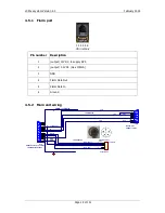
4.5.3
V5/V9/V80 vario unit wiring
1
6
7
4
9
5
SUBD15 Connector / female
V5
white
red
shield
black
yellow
GND
+12V
B
A
GND SHIELD
SC
1
9
2
10
3
11
4
12
5
13
6
14
7
15
8
B
A
SC switch
30 cm
50 cm
VP switch
VP
50 cm
(green)
(Brown)
OAT
1.5m
OAT
LABEL:OAT
LABEL: VARIO PRIORITY
LABEL:SC
LABEL:RS485
(pusti olupljen pospajkan kabel)
shield
CANH
CANL
INPUT2 - AIRBRAKES
INPUT1 - GEAR
INPUT3 - WATER BALLAST - VALVE
INPUT4 - FREE
12V IN
IN1
IN3
IN2
IN0
LABEL:IN-1
LABEL:IN-2
LABEL:IN-3
LABEL:IN-4
Free
Closed, when valve is closed
Closed, when Airbrakes are closed
Closed, when gear is down
50 cm
50 cm
50 cm
50 cm
1 2 3
G
N
D
LM335Z
GND SHIELD
GND SHIELD
GND SHIELD
GND SHIELD
GND SHIELD
GND SHIELD
RS485 - IN
SUBD9 / male
4.5.4
USB-D or Analog unit wiring
1
6
7
4
9
5
SUBD15 Connector / female
LX9000 VARIO UNIT
white
red
shield
black
yellow
GND
+12V
B
A
RS485 - IN
SPEAKER
SUBD9 / male
GND
+12V DC IN
SC
1
9
2
10
3
11
4
12
5
13
6
14
7
15
8
Data Out
Data In
B
A
RCA Jack Receptacle (CHINCH/Female)
SC switch
Speaker
30 cm
30 cm
50 cm
LABEL:AUDIO OUT
LX 9000 VARIO UNIT Wiring
VP switch
VP
50 cm
(green)
(Brown)
DS1820
OAT
1.5m
OAT
LABEL:OAT
LABEL: VARIO PRIORITY
LABEL:SC
LABEL:RS485
shield
shield
4.5.5
Connecting vario unit
Vario unit is connected to main unit through RS485 bus. SC cable is used for external switch,
for switching between climb and cruise mode. In case that SC is connected to flaps switch,
VP (vario priority) is connected to switch on stick. Inputs IN1..4 are used to connect to gear
switch, airbrakes, etc...
4.6
Installation of Options
All options (Rear Seat Device, Remote Control, Compass Module & secondary vario
indicators) are prepared to be connected to the RS485 system bus by use of RS485 splitting
units. Installation of any option is plug-and-play and therefore requires only mechanical
Содержание LX90xx
Страница 2: ......
Страница 129: ...LX90xx system Version 4 0 February 2014 Page 129 of 151 ...

