


LION I/O Modules
▪
Safe Data Communication
45
8
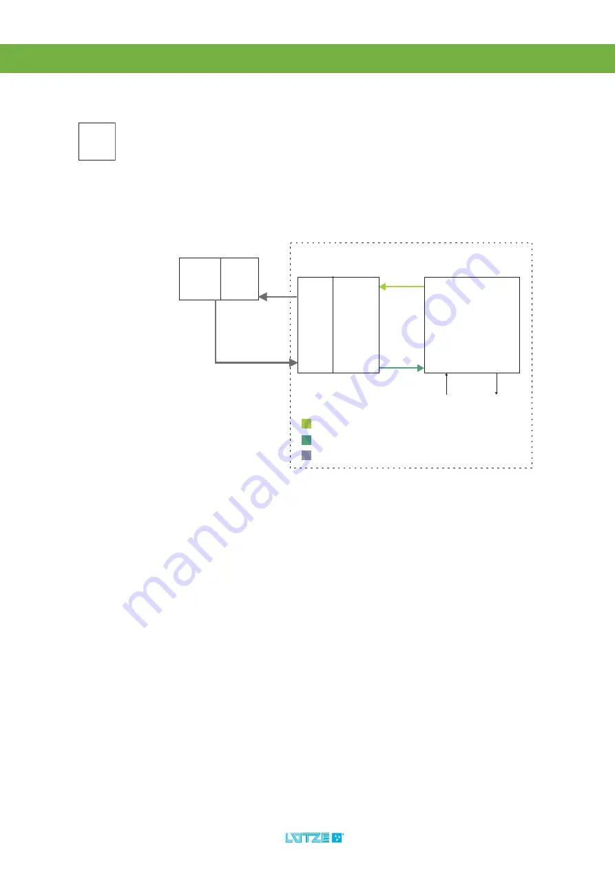
Safe Data Communication
8.1
General
In the system, the bus coupler communicates with the SIL2 I/O modules via
L-Bus
2
.
Input and output data are transferred. The SIL2 I/O modules get data from
connected sensores or transmit data to connected actuators, depending on the
module type.
Process Data – PV-Names/Signals
The data which are transferred consist process and status information, depending
on the process data image of each module (see also the instructions of the LION
I/O modules). This data has to be mapped on the bus coupler‘s process variables
(PV-Names) and signals. Process data has to be marked as safe in the
configuration, because they will be specially handled in the SIL2 bus coupler. The
mapping is done in the LION Configuration Framework.
Ports
The process data are allocated to ports. Ports are consisting of different signals,
process variables and process diagnosis data. Every port has its own port ad-
dress and a defined length. Out of this data, the source and sink data, which will
be send on the MVB to the PLC, are generated. The data of the SIL2 modules will
be transformed to SDTv2 source data.
The SIL2 bus coupler and the PLC are communicating via MVB fieldbus. The
MVB communication includes the content, the transmitting and receiving of the
MVB slave telegram. The slave telegram contains all data of the port.
Depending on the direction (transmitting/receiving) sink (receiving data) or source
(transmitting data), different ports has to be configured. The transfer of the data
and the data has to be seen out of the direction of the MVB master, the bus
coupler is MVB slave. In the picture above, the PLC is the MVB master.
SIL
relevant
LION-011
The safe data communication of the SIL2 IO modules is only possible with a SIL2
bus coupler and a connected SIL2 PLC. For the data communication, a safe
protocol is needed to reach the SIL2 level.
The outputs do only reach SIL2 if the connected actuator has an plus/minus
switching architecture. If its is connected one channel plus switching, only SIL1
is reached.
B
uscoup
ler
S
I
L2
SOURCE PORT
SINK PORT
P
V-
N
AME
S/S
IG
N
A
LS
P
V-
N
AME
S/S
IG
N
A
LS
I
NP
UT DATA
O
UT
P
UT DATA
S
AFE
O
UT
P
UT an
d
I
NP
UT DATA v
i
a MVB (
S
DTv
2
P
R
O
T
OCOL
)
MVB
PLC
S
I
L2
L
-B
us
2
MVB
SINK PORT
SOURCE PORT
I
/O
DI
/
D
O
S
I
L2
P
R
OC
E
SS
DATA IMAGE
S
en
so
r
A
c
t
u
at
o
r
P
R
OC
E
SS
DATA IMAGE
L
-B
us
2
S
DT-
S
I
N
K-DATA
S
DT-
SO
UR
C
E-DATA
SDT
-
SO
UR
C
E-DATA
SDT
-
S
I
N
K-DATA
S
DTv
2
P
r
o
t
oco
l
S
DTv
2
P
r
o
t
oco
l


