• System communication uses IEC PELV wiring.
• Follow all local and national electrical codes when
installing IEC PELV wiring with line voltage/mains
wiring.
• Each terminal accepts up to two 1.0
mm
2
wires.
• Total length of control link must not exceed
610 m.
• Make all connections in the control unit’s wallbox.
• Wiring can be T-tapped or daisy-chained.
• IEC PELV 24 V
150 mA.
System Limits
The QS wired communication link is limited to 100
devices or 100 zones.
The GRAFIK Eye
®
QS control unit supplies 3 Power
Draw Units (PDUs) on the QS link. Refer to the
QS Link Power Draw Units specification submittal
(Lutron PN 369405) for more information concerning
Power Draw Units.
®
Wiring the GRAFIK Eye
®
QS Control Unit:
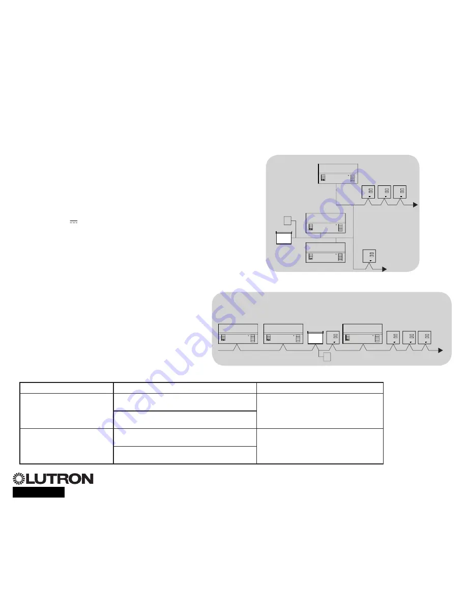
QS Link Control Wiring Details
QS smart
power
panel
LUTRON
LUTRON
LUTRON
LUTRON
LUTRON
LUTRON
T-Tap Wiring Example
GRAFIK Eye
®
QS
control unit
Sivoia
®
QS
window
treatment
seeTouch
®
QS
wallstation
LUTRON
LUTRON
LUTRON
LUTRON
LUTRON
LUTRON
GRAFIK Eye
®
QS
control unit
Sivoia
®
QS
window
treatment
seeTouch
®
QS
wallstations
Daisy-Chain Wiring Example
QS smart
power panel
GRAFIK Eye
®
QS
control unit
For additional information, see the complete installation and operation guide at
www.lutron.com/qs
GRAFIK Eye
®
QS Control Unit Quick Installation and Operation Guide 7
Wire Sizes (
check compatibility in your area)
QS Link Wiring Length
Wire Gauge
Lutron Cable Part Number
Less than 153 m
Power (terminals 1 and 2)
1 pair 1.0 mm
2
GRX-CBL-346S (non-plenum)
GRX-PCBL-346S (plenum)
Data (terminals 3 and 4)
1 twisted, shielded pair 0.5 mm
2
153 to 610 m
Power (terminals 1 and 2)
1 pair 4.0 mm
2
GRX-CBL-46L (non-plenum)
GRX-PCBL-46L (plenum)
Data (terminals 3 and 4)
1 twisted, shielded pair 0.5 mm
2


