background image

®

Wiring the GRAFIK Eye

®

 QS Control Unit:

Line Voltage Wiring Details

•  Use properly certified cable for all line 

voltage/mains cables.

•  Proper short-circuit and overload 

protection must be provided at the 

distribution panel. You can use up to a 

20 A circuit breaker for your installation.

•  Install in accordance with all local and 

national electrical codes.

•  IEC PELV terminals may be temporarily 

unplugged for ease of IR, occupancy 

sensor, and control wiring.

• 

Notice: Risk of damage to unit . 

Do not 

connect line voltage/mains cable to IEC 

PELV terminals.

Step 1: Install wallbox. 

Mount an 

89 mm deep 4-gang U.S. wallbox on a 

dry, flat indoor surface that is accessible 

and allows for system programming 

and operation. Allow at least 110 mm 

clearance above and below the faceplate 

to ensure proper heat dissipation. Allow  

25 mm for faceplate overhang on all 

sides. 

Note:

 4-gang wallbox available from 

Lutron; P/N 241400.

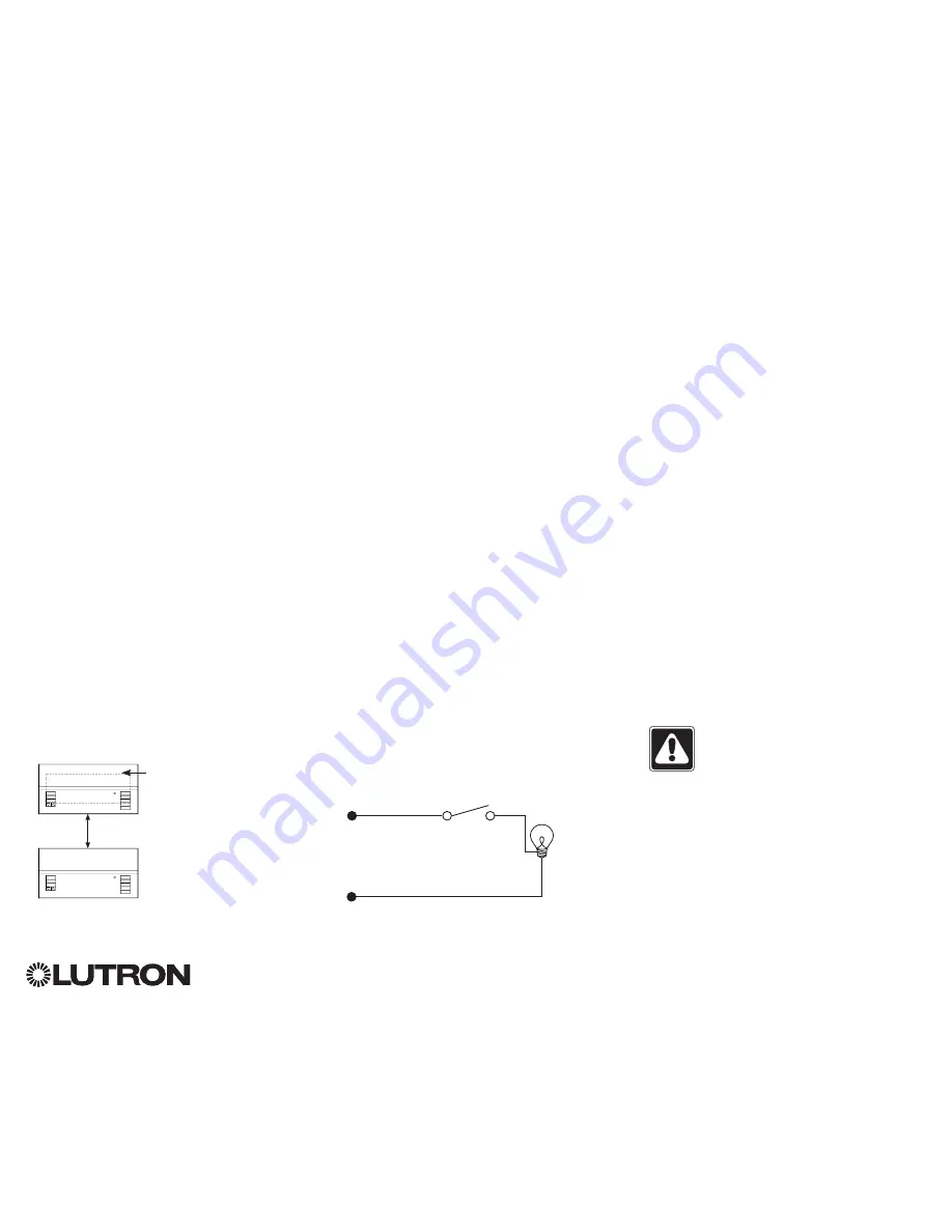
Step 2: Test load wiring.

•  Turn power OFF at the circuit breaker or 

fuse box.

•  Connect a standard light switch between 

the live lead and load wire to test the 

circuit.

•  Turn power ON and check for short or 

open circuits. If load does not operate, 

the circuit is open. If the circuit breaker 

trips (fuse blows or opens), a load short 

may exist. Correct short or open circuits 

and test again.

Step 3: Check control unit wiring.


Earth/ground terminal connection must 

be made as shown in line voltage wiring 

diagrams.


Do not mix different load types on the 

same zone.

• 

Follow all local and national electrical 

codes when installing IEC PELV wiring 

with line voltage/mains wiring.

WARNING!


Shock hazard.

 May 

result in serious injury or death. 

Always turn off circuit breaker or 

remove main fuse from power line 

before doing any work. Before 

connecting the loads to the 

GRAFIK Eye

®

 QS control unit, test 

the loads for short-circuits.

Neutral

Hot/Live

Switch

Load

LUTRON

LUTRON

Faceplate overhangs 

wallbox on all sides;  

allow 25 mm

110 mm

For additional information, see the complete installation and operation guide at 

www.lutron.com/qs

GRAFIK Eye

®

 QS Control Unit Quick Installation and Operation Guide   4

Содержание QSGR-3PCE

Страница 1: ...Navigating Menus in Programming Mode 10 Wireless Mode 11 Zone Setup Assigning Load Types 12 Assigning Non Dim Load Type 12 Setting Load Types 13 Scene Setup Setting Zone Levels Fade Rates and Window...

Страница 2: ...evels Timeclock button Displays current timeclock info OK button Used for programming Infrared receiver For handheld remote use Master buttons Temporarily raise and lower lighting levels on unit USB t...

Страница 3: ...GRAFIK Eye QS Control Unit Overview of Line Voltage Mains Wiring 1 2 3 4 1 2 A B C 1 2 3 4 5 6 L N 4 0 mm2 each terminal 230 V Distribution Panel Line Voltage Mains Cables and Load Wiring 1 2 3 4 5 6...

Страница 4: ...F at the circuit breaker or fuse box Connect a standard light switch between the live lead and load wire to test the circuit Turn power ON and check for short or open circuits If load does not operate...

Страница 5: ...ntrol unit to properly recognize them Notice Risk of damage to unit GRAFIK Eye QS control units must be in stalled by a qual i fied electrician in accordance with all applica ble reg u la tions and bu...

Страница 6: ...rminals 3 and 4 Twisted shielded pair 0 5 mm2 each terminal 24 V 100 mA Common and power terminals 1 and 2 Two 1 0 mm2 each terminal for link 153 m Two 4 0 mm2 each terminal for link 153 610 m Do not...

Страница 7: ...mart power panel LUTRON LUTRON LUTRON LUTRON LUTRON LUTRON T Tap Wiring Example GRAFIK Eye QS control unit Sivoia QS window treatment seeTouch QS wallstation LUTRON LUTRON LUTRON LUTRON LUTRON LUTRON...

Страница 8: ...3 and 4 NOT terminal 2 shown by the letter B on the diagram Wiring can be T tapped or daisy chained For additional information see the complete installation and operation guide at www lutron com qs G...

Страница 9: ...tton The LED will light Press the zone raise and lower buttons Make sure the control unit is dimming all connected loads 3 Apply the protective overlay to the control unit Note When tightening mountin...

Страница 10: ...will either take you to the next menu or accept a setting you have selected When the screen displays a Yes No question the OK button is Yes Timeclock Button The Timeclock button functions as a back bu...

Страница 11: ...FIK Eye QS Wireless control unit will respond to any programming commands from nearby Lutron QS wireless and compatible products Ignore Programming default The GRAFIK Eye QS Wireless control unit will...

Страница 12: ...t zone Zone Setup Non Dim Load Type Load Type Set zones Saved Load Type Assigning Non Dim Load Type Zones assigned to non dim loads have three available configurations LOFO Last On First Off FOFO Firs...

Страница 13: ...ust be used with the control unit Zone ratings Not all zones must be connected however connected zones must have a minimum load of 40 W Maximum loads 10 A per unit 500 W per zone Maximum total lightin...

Страница 14: ...lay and the three middle LEDs for the zone will be lit to indicate this zone is unaffected by the scene the zone will not change when this scene is initiated When all zones are at the desired level pr...

Страница 15: ...of box functionality Doing so will remove its programming from the GRAFIK Eye QS control unit 7 Repeat the above steps for all desired sensors 8 Exit programming mode Associating wireless occupancy s...

Страница 16: ...ress OK Once a sensor has been assigned it will appear with an asterisk in the sensor list Repeat for additional sensors Note If wireless sensors are not found verify that they are associated correctl...

Страница 17: ...utomatically turn off the lights after a set time delay Disable this feature by setting the time delay to 0 disabled Range Disabled or 1 30 minutes default Disabled Zone Fade When in Zone Mode lights...

Страница 18: ...t level and then press the zone raise and lower buttons simultaneously for 1 second until the zone LEDs flash at the programmed preset level Repeat for all zones you wish to control with the Pico wire...

Страница 19: ...issipate about 2 of the connected load as heat No action is required Unit does not allow scene change or zone adjustments Unit is in wrong save mode Change to correct save mode QS device in system has...

Страница 20: ...TTEN CONSENT ARISING OUT OF OR IN ANY WAY RELATED TO THE INSTALLATION DEINSTALLATION USE OF OR INABILITY TO USE THE UNIT OR OTHERWISE UNDER OR IN CONNECTION WITH ANY PROVISION OF THIS WARRANTY OR ANY...

Отзывы: