3-26
CDD3000-HF Operation Manual
3 Installation
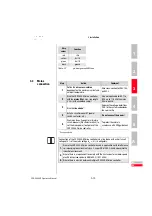
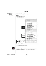
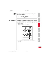
Parameters to evaluate the signals can be set for signal type, lines per
revolution and transmission ratio.
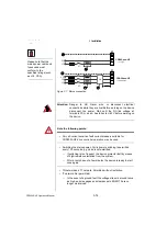
Figure 3.13 Master encoder input connection and signal description
A+
A-
B+
B-
Pulse
Direction
RS485
A
RS485
B
R
RS485
RS485
RS485
+5V
GND
CDD3000-HF- X5
CNC or CDD3000-HF
or TTL encoder
6
* For the CDD3000-HF the wave terminating resistor must
be connected externally
=
=
only f
or e
xter
nal
encoder
A+ 5
A- 9
B+ 8
B- 4
R+ 7
R- 3
+5V +10%
100 mA max.
2
1
GND


