background image

CDD3000-HF Operation Manual

3-11

3  Installation

DE
EN
FR
IT
ES
FR

1

2

3

4

5

A

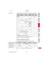
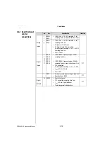
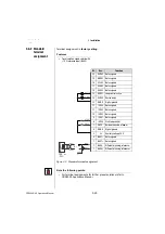
Pin assignment

You can enter your custom assignment in the columns for connector B.     

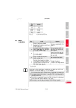
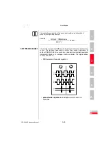
Technical data of LUST encoder cables

These cables are supplied ready made-up in various lengths.  

Connec-

tor A

Function

Sine/cosine

SSI 

function

HIPERFACE

®


function

Connec-

tor B

Wire 

colour

CDD3000-

HF X7

Custom

1

A-

A-

REFCOS

2

A+

A+

+COS

3

+5 V / 150 mA

+5 V / 150 mA

4

DATA+

Data+ RS485

5

DATA-

Data- RS485

6

B-

B-

REFSIN

7

Us 7-12V / 

100mA*

8

GND

GND

GND

9

R-

10

R+

11

B+

B+

+SIN

12

+5 V / (sensor)

+5 V / (sensor)

13

GND (sensor)

GND (sensor)

14

CLK+

15

CLK-

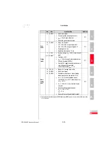
Outer and inner shield (if fitted) on both sides of housing

* To 250 mA with ex24 V (-5 %/+20 %) supply via terminal X2 permitted.

Table 3.5

Encoder cable pin assignment

KRY-KSxxx

1)

KGN-KSxxx

1)

KGS-KSxxx

1)

KGH-KSxxx

1)

drive controller type

CDD3000-HF

Motors with encoder system

R1, R2, R8,

K1, K2, K8

G1

G2, G3, G5

G6, G7

Festoon-compatible

yes

Table 3.6

Technical data of LUST encoder cables

Содержание CDD3000-HF

Страница 1: ...D CDD3000 HF Inverter Drive System 2 2 A 32 A EN EN FR IT ES Operation Manual...

Страница 2: ...V W RB RB L L1 L2 ACHTUNG Kondensatorent ladezeit 3 Min Betriebsanleitung beachten X5 X6 X7 X1 L3 U V W RB RB L L1 L2 H1 H2 H3 X4 X2 X3 ACHTUNG Kondensatorent ladezeit 3 Min Betriebsanleitung beachte...

Страница 3: ...m very quickly and easily Guide to quick starting 2 Simply follow the step by step tables in sections 2 3 4 Experience Plug n Play with the CDD3000 HF And away you go 1 Safety 2 Mechanical installatio...

Страница 4: ...ing a drive system Adaptation of the drive system to the application CANLust Communication Module Manual CANopen Communication Module Manual PROFIBUS DPCommunication Module Manual Project planning ins...

Страница 5: ...lead connection 3 4 3 3 Motor connection 3 5 3 3 1 Motor phase connection 3 6 3 3 2 Motor temperature monitoring 3 7 3 3 3 Holding brake if installed 3 8 3 3 4 production of encoder cables 3 8 3 4 Mai...
Страница 6: ...d encoder 4 11 4 3 4 Making basic settings 4 13 4 3 5 Setting function parameters 4 14 4 3 6 Safety functions 4 15 4 3 7 Motor filter 4 16 4 3 8 Switching frequency 4 16 4 3 9 Saving settings 4 17 4 4...

Страница 7: ...nual DE EN FR A Appendix A 1 Technical data A 2 A 2 Ambient conditions A 8 A 3 Project planning notes Cold plate A 9 A 4 Change in system load through use of a line choke A 10 A 5 UL approbation A 12...

Страница 8: ...CDD3000 HF Operation Manual...

Страница 9: ...pplied Rotating parts Hot surfaces Your qualification In order to prevent personal injury and damage to property only personnel with electrical engineering qualifications may work on the device The qu...

Страница 10: ...horised opening and incorrect intervention could lead to physical injury or material damage The warranty granted by LUST will become void 1 3 Responsibility Electronic devices are never fail safe The...

Страница 11: ...ate vicinity no drill chippings screws or foreign bodies drop into the device the vent openings are not covered over The device may otherwise be damaged 2 2 Mounting variants Step Action Comment 1 Ref...

Страница 12: ...ined This clearance A must be sufficient for the screwdriver to be inserted Note If the installation prevents the clearance A from being maintained the mounting set CDD order no 0927 0017 is available...

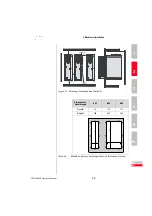
Страница 13: ...attention to the mounting clearances The contact surface must be metallically bright 3 Mount the other components such as the mains filter line choke etc on the backing plate Mains filter max 20 cm b...

Страница 14: ...crews 4 x M4 4 x M4 E 3 0 E1 with module 3 45 F 3 100 G 3 300 1 Additionally allow enough space at the bottom for the bending radii of the connecting cables 2 Corresponding to cold plate version with...

Страница 15: ...Clean the contact surface and coat it thinly and evenly with heat transfer compound The contact surface must be metallically bright 3 Mount the drive controller for highspeed drives vertically on the...

Страница 16: ...th 120 145 150 A 50 85 135 185 C 205 230 200 C with mounting set 230 255 C1 100 D 4 8 5 5 Screws 4 x M4 6 x M5 E 1 0 0 E1 with module 1 45 15 F 1 1002 G 1 300 1 Mounting clearances see Figure 2 2 2 Ad...

Страница 17: ...2 BG2 2 2 kVA CDD32 006 HF Cx x 90 97 W 0 05 650x460mm 0 3m 45 C1 40 C2 2 8 kVA CDD32 008 HF Cx x 110 120 W 0 05 650x460mm 0 3m 45 C1 40 C2 1 5 kVA CDD34 003 HF Cx x 70 85 W 0 05 None 45 C1 40 C2 2 8...

Страница 18: ...components such as the mains filter line choke etc on the backing plate Mains filter max 20 cm below the drive controller for highspeed drives 4 Continue with electrical installation in section 3 Not...

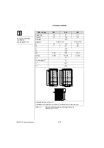
Страница 19: ...DE EN FR IT ES FR 1 2 3 4 5 A Figure 2 3 Mounting clearances see Table 2 5 Dimensions of breakthrough BG3 BG4 BG5 B width 75 125 175 H height 305 305 305 Table 2 4 Breakthrough for push through heat...

Страница 20: ...C1 200 D 4 8 4 8 4 8 Screws 8 x M4 10 x M4 10 x M4 E 1 10 E1 with module 1 10 F 1 100 2 G 1 300 1 Mounting clearances see Figure 2 3 2 Additionally allow enough space at the bottom for the bending rad...

Страница 21: ...les 3 8 3 4 Mains connection 3 13 3 5 Braking resistor RB 3 16 3 6 Control connections 3 17 3 6 1 Specification of control connections 3 18 3 6 2 Standard terminal assignment 3 20 3 6 3 Isolation 3 21...

Страница 22: ...rge time 3 minutes Pay attention to the operation manual ATTENTION temps de decharge du condensteur 3 min observer le mode d mploi ANTRI EBSTE CHNIK SN 000 0 00 00 000000 Typ Net z Aus g D 35 633 Lahn...

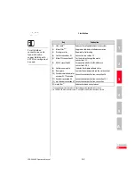
Страница 23: ...mission 3 Braking resistor1 Required for fast braking 4 Control connections X2 Connection see section 3 6 5 Motor PTC connection X3 For thermal monitoring of the motor see section 3 3 2 6 RS232 connec...

Страница 24: ...ins connection 10 mm Use grounding lead PE cross section according to cross section of mains leads 2 Also connect the grounding lead connections of all other components such as the line choke filter h...

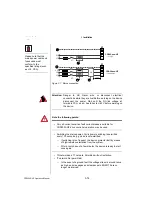
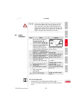
Страница 25: ...ke if fitted with separately shielded wires or with wires routed in the motor cable Mount shield at both ends to reduce interference emission 3 3 3 4 Connect the encoder by a ready made up cable to th...

Страница 26: ...e the motor and unit ends of the motor phases U V and W If the motor phases are incorrectly connected the CDD3000 HF drive controller will lose control over the motor and the motor may buck or acceler...

Страница 27: ...circuit dedection 20 the CDD3000 HF will note a short circuit at 50 For commissioning the correct type of temperature sensor used in the connected motor must be set up This measure is not necessary i...

Страница 28: ...n of servomotors from the LUST range Resolver Which resolver With the CDD3000 HF drive controller resolvers to the following specification can be evaluated Function Symbol Value min typ max Input X2 1...

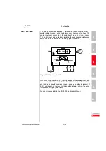
Страница 29: ...nectron type PLD 121 NV 171187 Cable type Cable festoon compatible e g Intercond 3MYI 17Z 10P 4x2x0 25 mm 2x1 mm or Lapp Unitronic FD CP TP 3x2x0 25 mm with UL approval Pin assignment You can enter yo...

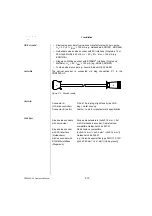
Страница 30: ...he optical encoder is connected via plug connection X7 to the CDD3000 HF Figure 3 5 Encoder cable Connector Cable types A B Connector A HF drive controller D Sub 15 pin plug High Density as VGA plug m...

Страница 31: ...FCOS 2 A A COS 3 5 V 150 mA 5 V 150 mA 4 DATA Data RS485 5 DATA Data RS485 6 B B REFSIN 7 Us 7 12V 100mA 8 GND GND GND 9 R 10 R 11 B B SIN 12 5 V sensor 5 V sensor 13 GND sensor GND sensor 14 CLK 15 C...

Страница 32: ...mum bending radius in fixed installation in flexible use 90 mm 40 mm 100 mm 90 mm Temperature range in fixed installation in flexible use 40 85 C 35 80 C 35 80 C 40 85 C Cable diameter approx 8 8 mm 8...

Страница 33: ...fe 4 Install a circuit breaker K1 power switch contactor etc Do not connect the power 5 Use mains fuses type gL or miniature circuit breakers trip characteristic C to cut the mains power to all poles...

Страница 34: ...lic power switching is permitted every 120 seconds jog mode is not permitted If switching is too frequent the device protects itself by means of high resistance isolation from the system After a rest...

Страница 35: ...t 523 VDE 0298 Part 4 the ambient temperature and the specified rated current of the CDD3000 HF drive controller Size Power range Mains filter BG1 4 1 0 11 8 kVA Internal 1 For supplementary component...

Страница 36: ...nd cycle duration Note The design of the braking resistor must be clarified at the project planning stage Please talk to us Attention In device version CDD3x xxx HF Wx x BR the braking resistor is bui...

Страница 37: ...age 3 2 2 Check whether you already have a SMARTCARD or a DRIVEMANAGER data set with a complete device setup If this is the case the control terminal assignment is different Please contact your projec...

Страница 38: ...ible Switching level Low High 4 8 V 8 V DC Sampling time 1 ms RIN 110 k Digital Inputs 8 9 10 11 12 ISD00 ISD01 ISD02 ISD03 ISD04 ISD00 ISD02 Frequency range 500 Hz sampling time 1ms ISD03 ISD04 Frequ...

Страница 39: ...5 6 13 24 V DGND 1 Auxiliary voltage UV 24 V DC short circuit proof Tolerance 20 Imax 100 mA overall also includes driver currents for outputs OSD0x External 24V supply to control electronics in case...

Страница 40: ...OSD01 Loop control active 14 OSD00 Device ready 13 DGND Digital ground 12 ISD04 Not assigned 11 ISD03 Not assigned 10 ISD02 Not assigned 9 ISD01 Not assigned 8 ISD00 Start loop control 7 ENPO Hardware...

Страница 41: ...lated thereby keeping interference away from the processor and the analog signal processing Figure 3 10 Voltage supply to I Os When selecting the cable note that the cables for the analog inputs and o...

Страница 42: ...housing with aluminium zink surface to improve the interference immunity factor as specified in IEC61800 3 environment 1 and 2 Drive controllers up to 17 A are equipped with integrated mains filters...

Страница 43: ...f the rotary encoder connected to the motor Accordingly pulses are delivered in two 90 offset signals A and B as well as a zero pulse R Figure 3 11 Encoder simulation signals looking onto the motor sh...

Страница 44: ...ification Interface RS422 Recommended wire cross section 0 14 mm e g 3x2x0 14 mm Max cable length 10 m Connector 9 pin D SUB socket min max Comments Output frequency 0 Hz 500 kHz Output voltage High l...

Страница 45: ...permits incremental reference input for loop control The reference generator is either the encoder simulation of another CDD3000 HF drive controller a standard commercially available incremental enco...

Страница 46: ...on ratio Figure 3 13 Master encoder input connection and signal description A A B B Pulse Direction RS485 A RS485 B R RS485 RS485 RS485 5V GND CDD3000 HF X5 CNC or CDD3000 HF or TTL encoder 6 For the...

Страница 47: ...on 3 6 Control connections Note When a HTL master encoder is in use both the encoder simulation and the master encoder input at X5 are inactive TTL encoder A rotary encoder with TTL level can also be...

Страница 48: ...Operation of a synchronous high frequency motor with a TTL encoder additionally requires setting of the commutation detection parameters For more information on this refer to the CDD3000 Application M...

Страница 49: ...alues 4 8 4 3 2 Selecting preset solution 4 9 4 3 3 Setting the motor and encoder 4 11 4 3 4 Making basic settings 4 13 4 3 5 Setting function parameters 4 14 4 3 6 Safety functions 4 15 4 3 7 Motor f...

Страница 50: ...Saving a data set to a SMARTCARD with KEYPAD A test run is essential see section 4 4 4 2 1 Serial commissioning with DRIVEMANAGER Precondition All CDD3000 HFs are fully connected The first drive is a...

Страница 51: ...cking on the icon always saves the current settings of the connected device Assign the file a name of your choice If you are using the Positioning fully programming preset also save the positioning pr...

Страница 52: ...e Saving a data set to a SMARTCARD Step Action Comment Display 1 Connect the KEYPAD to the CDD3000 HF of the first drive insert a SMARTCARD and switch on the power 2 Press stop return twice to call up...

Страница 53: ...of the next drive insert the SMARTCARD with the desired data set and switch on the power 2 Choose the CARD menu Load save with the SMARTCARD 3 Choose READ Load data set 4 Choose ALL and start the load...

Страница 54: ...rical connections while they are live Before working on the device disconnect the power Wait for the DC link capacitors to discharge Work may only be carried out on the device when the residual voltag...

Страница 55: ...7 4 Commissioning DE EN FR IT ES FR 1 2 3 4 5 A Open the main window Adjust CDD3000 Figure 4 1 Main window for the various settings in the DRIVEMANAGER Continue with DRIVEMANAGER CDD3000 HF setup or...

Страница 56: ...r speed values The CDD3000 HF provides the possibility to evaluate all nominal and actual speed values in the units Hz or rpm The desired unit can be set under the option Selection of display unit All...

Страница 57: ...set solution can optionally be controlled via the control terminals or over a field bus The preset solutions are Torque control 10V reference TCT_1 Speed control with external position control SCT_1 S...

Страница 58: ...hing your application The various screens list the application and functional features offered by the individual solutions Figure 4 4 Selection of preset solution Note For detailed information on pres...

Страница 59: ...rotection tab is correctly set and that the control circuits of the drive are preset Note The torque controller is set up optimally so no further adjustments are necessary The setting of the speed con...

Страница 60: ...t engineer on this Setting of the rotary encoder The rotary encoder connected to the motor is set up on the Encoder tab Resolvers are assigned the abbreviation Rx encoders Gx The encoder used is enter...

Страница 61: ...display under nist Actual speed must indicate a positive speed in clockwise rotation and a negative speed in counter clockwise rotation If the speed is incorrect the following points must be checked s...

Страница 62: ...tings can also be made In contrast to the basic settings the functions are independent of the preset solution Example Setting max torque The required functions such as the maximum torque can be progra...

Страница 63: ...unction can be used to enter further limit values for the max speed or the overspeed threshold besides the maximum torque Please check also the data for motor protection in the motor and transducer fu...

Страница 64: ...capacitance value is entered under Sine filter If only a motor choke is used this must be entered in the field Motor choke irrespective of the motor type 4 3 8 Switching frequency For high frequency...

Страница 65: ...ames e g mydata with the appropriate extension 00D The device data can be assigned a description prior to saving Continue with Test run see section 4 4 DRIVEMANAGER CDD3000 HF setup or Active device C...

Страница 66: ...such as pulleys couplings or the like Preset solution torque control In this preset solution the drive must not be run without load torque otherwise the motor shaft would accelerate uncontrolled up to...

Страница 67: ...esponse Now you can assess the drive response with the aid of step responses which can be recorded using the DRIVEMANAGER s digital scope function Select the following four recording variables 0 Speed...

Страница 68: ...am With resolvers the overshoot of the actual speed should be around 20 with sin cos incremental encoders around 30 referred to the reference value Make sure the drive system exhibits small signal res...

Страница 69: ...m the diagram it is to be assumed that the motor data set was selected incorrectly or the cabling is faulty Check the individual steps from Section 3 Installation and Section 4 3 Initial commissioning...

Страница 70: ...capacitor disscharge time 3 minutes Pay attention to the operation manual ATTENTION temps de decharge du condensteur 3 min observer le mode d mploi For more information refer to the DRIVEMANAGER Manu...

Страница 71: ...from device to file Active device Save device settings to Load settings from file into device Active device Load device settings from Bus initialization change settings Disconnect from device Cut all...

Страница 72: ...tion or braking ramp active 6 Bar graph display 10 digit Call up menu branches or parameters save changes start in Control drive mode Quit menu branches cancel changes stop in Control drive mode Selec...

Страница 73: ...ions 1 Select PARA menu 2 Select desired subject area with cursor keys and confirm with start enter 3 Select desired parameter with cursor keys pay attention to user level 4 The current value is displ...

Страница 74: ...n all parameters are always saved to the SMARTCARD For read operations either all parameters or only parameters for motor setup per read operation can be read in Function Meaning READ ALL Read all par...

Страница 75: ...5 6 User errors in SMARTCARD operation 5 5 5 7 Errors in power switching 5 5 5 8 Reset 5 6 5 1 LEDs At the top right of the CDD3000 HF there are three status LEDs coloured red H1 yellow H2 and green...

Страница 76: ...er response warning HALT 1 Signal error and disable power stage STOP 2 Signal error quick stop and wait for cancellation of start signal LOCKH 3 Signal error disable power stage and secure against res...

Страница 77: ...erload shut off Short circuit ground fault Check cabling of connections check motor coil check neutral conductor and grounding see also section 3 Installation Device setup not correct Check parameters...

Страница 78: ...r button In control via fieldbus set Reset error bit in bus control word Starting the drive after an error Cancel start signal and reapply it With programmed auto start function In error responses 1 a...

Страница 79: ...Card must not be read in current state Reset start signal ERROR Invalid password Enter correct password Table 5 2 KeyPad USER ERROR Reset with start enter Error Meaning Remedy ERR91 SMARTCARD write pr...

Страница 80: ...e entered there Factory setting KEYPAD Press both KEYPAD cursor keys simultaneously during CDD3000 HF power up to reset all parameters to their factory defaults and the system is reinitialized DRIVEMA...

Страница 81: ...DE EN FR IT ES FR 1 2 3 4 5 A A Appendix A 1 Technical data A 2 A 2 Ambient conditions A 8 A 3 Project planning notes Cold plate A 9 A 4 Change in system load through use of a line choke A 10 A 5 UL a...

Страница 82: ...4 1 A 5 7 A Peak current 1 8 x IN for 30 s 4 3 A 7 2 A 9 9 A 12 8 A 4 0 A 7 4 A 10 3 A Rotating field frequency 0 1600 Hz Switching frequency of power stage 4 8 12 16 kHz Input mains side Mains volta...

Страница 83: ...A 14 A 17 A 24 A 32 A Peak current 1 8 x IN for 30 s 14 A 18 A 25 A 31 A 43 A 58 A Rotating field frequency 0 1600 Hz Switching frequency of power stage 4 8 12 16 kHz Input mains side Mains voltage 3...

Страница 84: ...ible under which changed background conditions refer to the following characteristic diagrams and tables Current capacity of drive controllers 1 Continuous 2 Intermittent 5 Hz rotating field frequency...

Страница 85: ...3 2 4 3 4 3 3 8 3 2 CDD32 004 HF Cx x1 1 6 4 8 12 16 4 4 3 5 3 7 2 7 2 6 3 5 4 7 2 7 2 6 3 5 4 CDD32 006 HF Cx x1 2 2 4 8 12 16 5 5 5 5 4 9 4 3 9 9 9 9 7 1 7 7 9 9 9 9 8 8 7 7 CDD32 008 HF Cx x1 2 8 4...

Страница 86: ...2 1 6 1 0 4 4 1 8 1 1 4 4 2 9 1 8 CDD34 005 HF Cx x1 2 8 4 8 12 16 4 1 4 1 3 2 2 4 4 1 3 6 7 4 7 4 5 8 4 3 7 4 7 4 5 8 4 3 CDD34 006 HF Cx x1 3 9 4 8 12 16 5 7 5 7 4 1 2 6 5 7 5 7 10 3 10 3 7 4 4 7 1...

Страница 87: ...ture 45 C at power stage switching frequency 4 kHz 40 Catpowerstageswitchingfrequency 8 12 16 kHz 1 With heat sink HS3 or additional cooling surface 2 Mains voltage 3 x 400 V 10 3 Mains voltage 3 x 46...

Страница 88: ...ength to IEC 68 2 6 Vibration 0 075 mm in frequency range 10 57 Hz 1 g in frequency range 57 150 Hz Protection Device IP20 NEMA 1 Cooling method Cold plate IP20 Push through heat sink IP54 3 15 kW Tou...

Страница 89: ...Heat sink Housing BG 1 2 BG 3 BG 4 BG 5 1 0 to 3 9 5 4 to 6 9 9 7 to 11 8 16 6 to 22 2 approx 65 approx 70 approx 75 approx 80 approx 35 approx 30 approx 25 approx 20 Active cooling area Size Device r...

Страница 90: ...Mains current effective 8 5 A 6 23 A 27 Commutation notches referred to the mains voltage 28 V 8 V 70 Life of the DC link capacitors Nominal life 2 to 3 times nominal life 100 to 200 Change in system...

Страница 91: ...eed electric drives standard EN61800 3 IEC1800 3 With a dc link between multiple drive controllers Characteristics of environment class 3 include Mains voltage fluctuations 10 UN Short time interrupti...

Страница 92: ...ntrollers can typically be overloaded with 1 8 x IN for 30 s The effective servo capacity utilization Ieff IN must never be greater than IN rated current Tightening torque of grounding lead terminal N...

Страница 93: ...ction Mains power cable 10 mm Grounding lead PE cross section of at least 10 mm or lay a second electrical conductor parallel to the existing grounding lead because the operational leakage current is...

Страница 94: ...e time 3 minutes Pay attention to the operation manual ATTENTION temps de decharge du condensteur 3 min observer le mode d mploi X9 X8 H1H2H3 X1 X2 X3 X4 X1 L3 U V W L RB L L1 L2 ACHTUNG Kondensatoren...

Страница 95: ...iagnosis Fault rectification 5 1 Digital scope function 4 19 Dimensional drawings Push through heat sink 2 10 Wall mounting 2 4 Dimensional drawings cold plate 2 6 Disconnect 4 3 DriveManager 4 9 4 22...

Страница 96: ...erminal boxes 3 7 Mounting clearances 2 3 collar 2 8 height A 8 plate 2 3 seal 2 8 set CDD 2 2 variants 2 1 Mounting and cooling variants 2 1 N Notes on operation 2 1 O Optical encoders Cable 3 10 Ove...

Страница 97: ...Standards 1 2 Step response 4 21 Strength mechanical A 8 surge strength class A 12 Switching frequency 4 16 T Technical data A 2 Temperature 2 7 Temperature range A 8 Test run 4 18 Thermal monitoring...

Страница 98: ...CDD3000 HF Operation Manual Appendix B Index A 24...

Страница 99: ...ebsger te als eine Komponente in ihrer Maschine Anlage einsetzen dann ist der Geltungsbereich der Norm f r die komplette Maschine Anlage zu pr fen limits for harmonic current emissions Our frequency i...

Страница 100: ...GmbH Gewerbestrasse 5 9 35633 Lahnau Germany Tel 49 0 64 41 9 66 0 Fax 49 0 64 41 9 66 137 Internet http www lust tec de e mail info lust tec de ID no 0998 00B 1 00 03 2005 We reserve the right to ma...

Отзывы: