3-24
CDD3000-HF Operation Manual
3 Installation
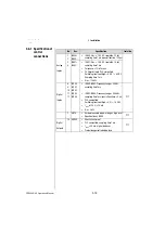
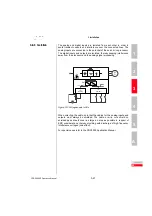
The resolution of the encoder simulation is adjustable when a resolver is
used; when incremental encoders are used it corresponds to the
resolution of the connected encoder. Rotary encoders of type G2-G6 emit
no zero pulse.
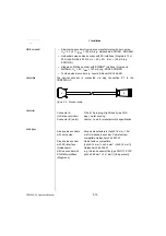
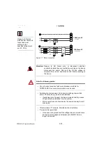
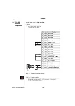
Figure 3.12 Encoder simulation connection and signal description
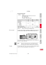
Electrical specification
Interface: RS422
Recommended wire cross-section >0.14 mm²
(e.g. 3x2x0.14 mm²)
Max. cable length 10 m
Connector: 9-pin D-SUB, socket
min.
max.
Comments
Output frequency
0 Hz
500 kHz
Output voltage
•
High level
•
Low level
•
Differential
2.5 V
-
2.0 V
-
0.5 V
-
(I
OH
= -20 mA)
(I
OL
= 48 mA)
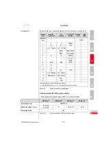
Table 3.9
Encoder simulation electrical specification
RS485
A
A+ 5
RS485
B
R
RS485
RS485
RS485
RS485
4 x 2 x 0,14 mm²
+5V 6
GND 1
GND
-X5
CDD3000-HF
CNC or CDD3000-HF*
* CDD3000-HF does not include wave terminating resistor.
It must be wired externally.
=
=
A- 9
B+ 8
B- 4
R+ 7
R- 3
+5V +10%
100 mA max.
2

