


3.1
Introduction of Live View
Live view shows you the video image getting from each camera in real time. The DVR will automatically enter
Live View mode when powered on. It is also at the very top of the menu hierarchy, thus hitting the ESC many
times (depending on which menu you’re on) will bring you to the Live View mode.
Live View Icons
In the live view mode, there are icons at the right top of the screen for each channel, showing the status of the
record and alarm in the channel, so that you can know whether the channel is recorded, or whether there are alarms
occur as soon as possible.
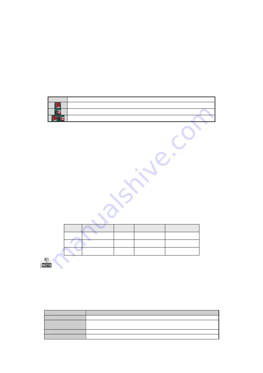
Table 3. 1
Description of Live View Icons
Icons
Description
Alarm (video loss, tampering, motion detection or sensor alarm)
Record (manual record, schedule record, motion detection or alarm triggered record)
Alarm & Record
3.2
Operations in Live View Mode
In live view mode, there are many functions provided. The functions are listed below.
•
Single Screen:
show only one screen on the monitor.
•
Multi-screen:
show multiple screens on the monitor simultaneously.
•
Auto-switch:
the screen is auto switched to the next one. And you must set the dwell time for each screen on
the configuration menu before enabling the auto-switch. Menu>Configuration>Live View>Dwell Time.
•
Start Recording:
normal record and motion detection record are supported.
•
Quick Set:
select the output mode to Standard, Bright, Gentle or Vivid.
•
Playback:
play back the recorded videos for current day.
•
Aux/Main output switch:
the DVR checks the connection of the output interfaces to define the main and
auxiliary output interfaces. When the aux output is enabled, the main output cannot do any operation, and
you can do some basic operation on the live view mode for the Aux output.
The priority level for the main and aux output is HDMI/VGA>CVBS. See the table below.
Table 3. 2
Priorities of Interfaces
S.N
VGA/HDMI
CVBS
Main output
Auxiliary output
1
√
√
VGA/HDMI
CVBS
2
√
×
VGA/HDMI
3
×
√
CVBS
√
means the interface is in use,
×
means the interface is out of use or the connection is invalid. And the HDMI,
VGA and CVBS can be used at the same time.
3.2.1
Using the Mouse in Live View
Table 3. 3
Mouse Operation in Live View
Name
Description
Menu
Enter the main menu of the system by right clicking the mouse.
Single Screen
Switch to the single full screen by choosing channel number from the dropdown
list.
Multi-screen
Adjust the screen layout by choosing from the dropdown list.
Previous Screen
Switch to the previous screen.
Available from A1 Security Cameras
www.a1securitycameras.com email: [email protected]
Содержание LTD8316T-ET
Страница 78: ...Chapter 7 Backup Available from A1 Security Cameras www a1securitycameras com email sales a1securitycameras com...
Страница 104: ...Chapter 10 VCA Search Available from A1 Security Cameras www a1securitycameras com email sales a1securitycameras com...
Страница 123: ...Chapter 12 HDD Management Available from A1 Security Cameras www a1securitycameras com email sales a1securitycameras com...
Страница 145: ...Chapter 15 Others Available from A1 Security Cameras www a1securitycameras com email sales a1securitycameras com...
Страница 153: ...Chapter 16 Appendix Available from A1 Security Cameras www a1securitycameras com email sales a1securitycameras com...


