Logosol Multifunctional Servo Drive LS-231g2SB
Doc # 712231006 / Rev. B, 12/26/2017
Logosol, Inc.
•
•
•
•
2833 Junction Ave., Ste. 101
•
•
•
•
San Jose, CA 95134
•
•
•
•
Tel: (408) 744-0974
•
•
•
•
www.logosolinc.com
28
Setting the drive in dual servo loop mode
The drive should be initialized in single servo loop mode before setting it to dual loop mode.
1. Turn off the power supply.
2. Connect the master encoder and the dual loop master encoder interface module LS-2311
accordingly to one of the sample applications described earlier.
3. Turn on the power supply and run LDCN Utility.
4. While still in single loop mode, run the motor and make sure the auxiliary encoder position on the
screen changes.
5. Click
Motor Panel
button.
6. Select
Master Encoder
in the
Position Feedback
radio group and click
Set
button.
Note:
The dual loop mode is available only in LDCN mode and in the standard Analog Input mode. Switching
between these two modes does not change the single/dual loop mode. However, setting the drive in any
other mode sets the drive in single loop mode.
Mode Selection
Various modes can be set using
Change Device Mode
button
.
Clicking this button activates a menu
with all possible modes of the controller. After setting the device mode, the PID parameters and all
other mode specific parameters should be set and saved to the non-volatile memory of the drive.
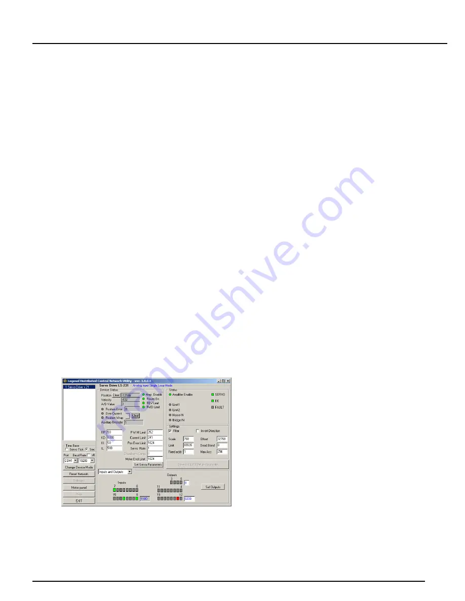
When an analog input mode is selected, set analog input parameters.
Filter
enables/disables filtering
of the analog input.
Invert direction
can be used to invert the motor direction.
Scale
is the factor used
to convert the analog input value (-32768 to 32767) to velocity. For example, scale of 10 produces
maximum velocity of 327670 or 97653 encoder counts per second (327670 / 3.3554432 = 97653). The
offset
determines the zero analog input and is usually set to 32767 – middle of the whole range.
Limit
is the maximum analog value.
Deadband
limits the minimum non-zero value thus reducing the
oscillations at zero velocity.
Acceleration
value determines how quickly the commanded velocity will
be reached. For example, a value of 256 corresponds to 1,490,116 encoder count/s/s (256 /
0.00017179869).
In all step modes, the
step rate
should be set. It represents the factor between steps and encoder
counts.
Fixed address should be set to a value between 1 and 31. It is recommended to use different values
for each drive in the network.


