ACS-CB-SENS - MANUAL // PAGE 13
6.3 NOTES FOR ASSEMBLY
NOTICE
In this configuration, the RJ10 Connector of the External Collision Sensor may only
be connected to the ACS-CB-SENS. Connecting the External Collision Sensor to other
devices or Plug Ports, including external telecommunication ports, may damage
the Sensor irreparably. Contact LOGICDATA if you are unsure whether the External
Collision Sensor is compatible with your device.
INFO
Exact dimensions for the LOG-PRT-DMS and ACS-CB-SENS can be found in the prod-
uct's datasheet.
6.4 MOUNTING THE ACS-CB-SENS
NOTICE
Ensure the ACS-CB-SENS is mounted in a place from which the cables can easily reach
the Control Box and LOG-PRT-DMS Sensor. Stretching or straining cables or connectors
may lead to system damage.
INFO
Screw specifications
The Mounting Screws should hold the unit safely and securely in place. Exact specifica-
tions can be provided by LOGICDATA on request.
1. Position the ACS-CB-SENS under the table top and mark the position of the Mounting Points.
2. Drill the holes for the Mounting Screws into the Table Top at the marked points.
3. Use the screwdriver and 2 Mounting Screws to attach the ACS-CB-SENS at the drilled holes.
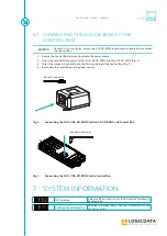
Fig. 3:
Mounting the ACS-CB-SENS


