


Doc. Ref.No: Q875-0143/ENG
Issue 2
Met 30+ Operating Manual
12/01/10
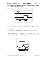
usual value of the input (as shown by the 0 or 1) is low (0), and when the photocell is
blocked the input should go high (1). The ‘Gating Photocell’ (G) can also be changed
to trigger of the leading or trailing edge of the pulse. A (‘>’) indicates a leading edge
trigger and a (‘<’) indicates a trailing edge trigger.
On entry to the option the letter 'T' will be flashing. Use the / keys to scroll the list
of timer inputs. When the desired input is flashing, press SELECT. The input can
now be disabled/enabled by pressing the or key. Press SELECT to allow
adjustment of the polarity (active high/low).
Change the polarity so that the timer input is 0 when the photocell isn't blocked.
Press SELECT. To exit this option press the / keys until 'X' is flashing and press
SELECT.
Syschek
allows the systemchek time to be changed. This is only relevant when one
or both systemcheks are enabled in Option Inputs.
When the reject relay is activated two timers are started, one for the product
systemchek and one for the reject systemchek. If a signal from the relevant
systemchek photocell is not received within the "systemchek time" then the fault
relay is activated, and will remain activated until the detector is reset.
Aux.
allows the fifth timer input (CN13 on the power supply) to be used in a variety
of applications, for example as an air failure detector or bin full sensor.
To use this facility proceed as follows: first enable the auxiliary input in option Inputs.
Then select option Aux. Select the message that most clearly describes what the
input is being used for, by using the and keys to change the message and
SELECT to accept it.
Now select the "Aux. active time". This is the length of time for which the auxiliary
input needs to be high (active) continuously before the software drives the output
relay. For a "bin full" sensor the active time might be a couple of seconds. Press
SELECT when the correct time has been chosen.
Finally, choose which output relay to drive. Use the and keys to change the
relay and SELECT to confirm the choice. Although there is a choice of five options
for which relay to drive (including none), the two most useful are: warning (e.g. for
bin full ) and fault (e.g. for air failure). Note that timer T6 cannot be assigned any
options.
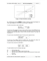
5.5.3 Vibration Setup (v) :
When the MET 30+ metal detector leaves the factory, the Test Setup phase angle is
set to same angle as vibration and calibrated to 0 degrees.
This option enables adjustment of this angle, which may be required if some of the
metal detector components have to be repaired. When this option is set the following
is displayed:
File Name: Q875-0143 ENG Iss2 Met30+ Operating.doc
Page 27 of 58