background image

ⱥㄒ㸭(1*/,6+

12

RE-ASSEMBL

Y

9

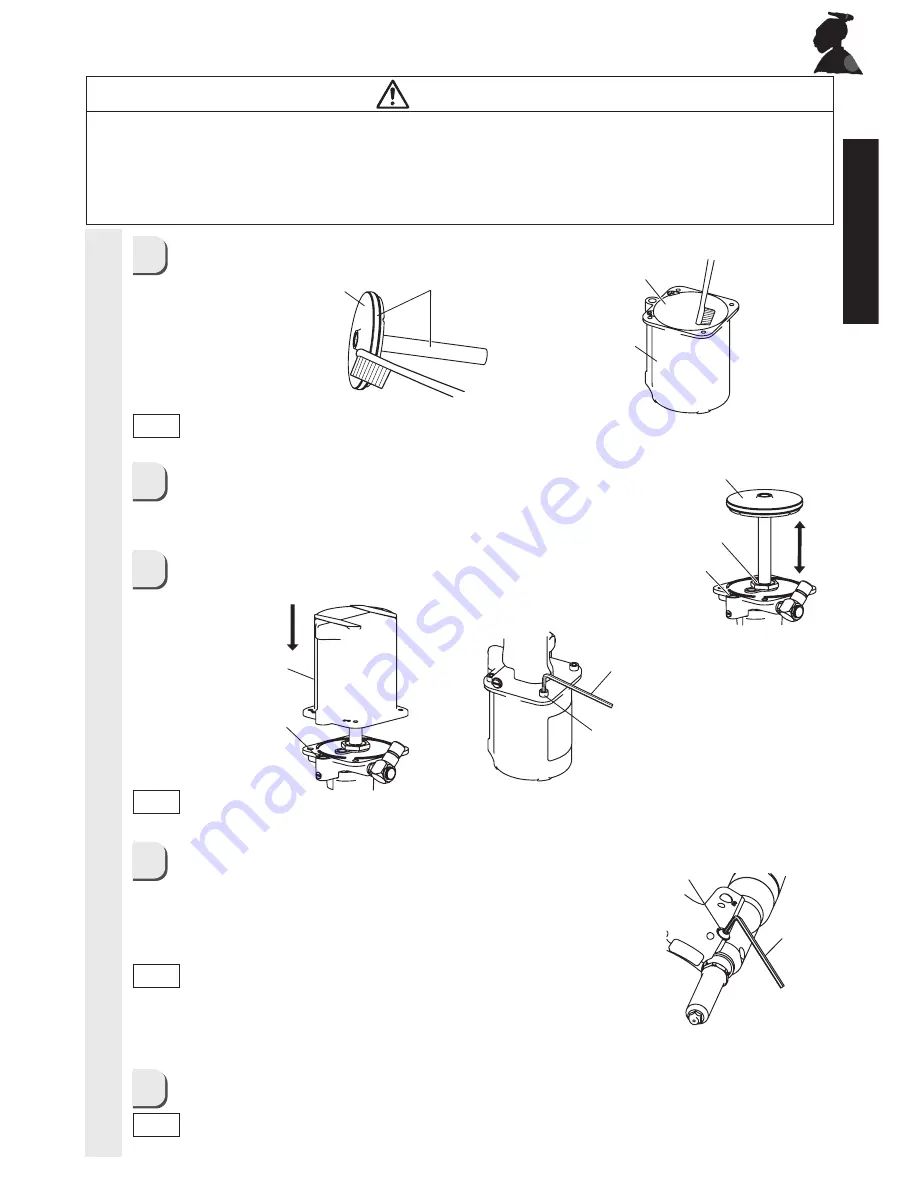
Push and insert the Air Piston Unit into the oil supply 
port and manually perform a piston motion for several 
times. Wipe off hydraulic oil spilling out of the oil 
supply port.

Attach the Cylinder Cup on the Air Piston Unit, and 
keeping pressing it down tighten the 4 hex socket 
screws.

After assembled Frame Head with Frame A, turn the unit 
as the Bleed Plug (hex socket bolt) comes to the upper side.
Then, loosen it using a hex key wrench (AF 4mm) in order to 
let excessive hydraulic oil and air (bubble) out.
After making sure that hydraulic oil no longer comes out, 
tighten the Bleed Plug again.

Wipe off hydraulic oil adhering to the main body or spilling out before use.

10

11

12

Air Piston Unit 

Oil supply port

Cylinder Cup

 Bleed Plug

Hex key 
wrench 
(AF 4mm)

O-ring SS9.5

Hex socket screw 
 (x4) 

O-ring

Hex key wrench 
(AF 4mm)

8

Apply grease to the O-Ring and rod of Air Piston Unit and to the inside of Cylinder 
Cup using brush.

Cylinder Cup

Apply grease

Apply grease

Air Piston Unit

ە

Avoid skin contact with substances such as hydraulic oil, lubricating oil and grease.

Such substances may cause inflammation of the skin. If they come into contact with your skin, 
wash the affected area thoroughly.

ە

Maintain the tool with due care.

Refer to the Instruction Manual for details on replacing parts and attachments, otherwise injury may 
occur.

CAUTION

ە

Before assembling, be sure to apply lubricant such as grease to each sliding section.

ە

Recommended grease is Grease

JUDGH

 1~2.

Note

ە

Assemble in reverse order of disassembly. 

ە

Make sure the O-ring SS9.5 is surely set in the counterbore. 

Note

ە

Note that hydraulic oil may squirt out when you loosen the 

Bleed Plug.

ە

The work should be done by necessity after feeding hydraulic 

      oil.  Otherwise there may be detrimental to the tool in loading 
      rivet or breakage of Frame. 

Note

ە

During disassembly/assembly, be careful to prevent cutting dusts of metal and 

     other objects from getting into the hydraulic oil and Air Cylinder.

Note

Содержание R1A1

Страница 1: ... the copyright of this manual It is prohibited to publish copy or translate to other language without prior consent CONTENTS IMPORTANT SAFETY INSTRUCTIONS 1 NOMENCLATURE 4 TECHNICAL DATA 5 PREPARATION BEFORE USE 6 OPERATING THE AIR RIVETER 8 MAINTENANCE 9 EXPLODED VIEW 17 TROUBLESHOOTING 16 STORAGE 19 ORDERING PARTS 19 PARTS LIST 18 International Marketing Sales Division 12 8 Shijo cho Higashi Osa...

Страница 2: ...e ejected from the tool s nosepiece during use and cause serious injury 3 Alwaysattachthetank caseunitbeforeuse If you work without attaching the tank case unit there is a risk that the mandrel of rivet that has been cut is not discharged and will be clogged inside exhaust pipe causing a fault of the equipment Also these mandrels may be ejected from the tool s nosepiece during use and cause seriou...

Страница 3: ...cur 11 Keepthehandgripalwaysdryandclean andavoidadhesionofoilandgrease Otherwise the grip may slip from your hand resulting in falling of the unit 12 Donotleavethefloorlitteredwithcut mandrels Cut mandrels are dangerous because their ends are sharp Stepping on them is also dangerous easily causing a slip and fall accident 13 Usethetoolcarefullyandconcentrateoncorrectoperationatalltimes Use the too...

Страница 4: ...ose hoses and fittings 33 The regular preventative maintenance shall be carried out for instance after a specilfied time of operation a specified number of cycles operations or a stated number of times per year 34 When you handle hydraulic oil or grease obtain the Safety Data Sheet SDS from the supplier and follow the described instructions 35 When disposing this tool please follow the regulations...

Страница 5: ... Grip Cover Vacuum Button Cylinder Cap Cylinder Cup Jaw Pusher Spring Rotary Joint Screw size Parallel pipe thread G1 4 Nosepiece FRAMEHEADINTERNALPARTS Jaw Pusher O ring P6 O ring P9 O ring S10 Guide Tube SUS Jaw Case CJM Ultra Jaws M Jaw Case Head Frame Head CJM Nosepiece chamfered ...

Страница 6: ...32 3 16 Operating environment Temperature Relative humidity Sound Pressure level Lpa Vibration Emission value The date of manufacture Serial number Display example N Y 1 2 3 4 Warning Label AF22mm Airintake Rotaryjoint 4Υ to 35Υ 80 RH max No condensation 73 dB Size of screw G1 4 PF1 4 Less than equal to 2 5m sec2 ȭ ȭ ȭ ە Product specifications and design are subject to change for improvement witho...

Страница 7: ...inside exhaust pipe causing a fault of the equipment Also these mandrels may be ejected from the tool s nosepiece during use and cause serious injury WARNING ە When you turn the Vacuum Button ON air comes out of the Exhaust Port on the side of the Tank Case Unit ە The Exhaust Port can face to any of the 4 directions so change the direction as your preference Note ە Adjust the drip feed amount of t...

Страница 8: ...parts may occur If the pressure is too low some size of the rivet may not be correctly installed cut Note ە Refer to Jaw maintenance on page 9 for details on replacing the guide tube Note ە Shaded areas indicate parts which are installed in the tool as standard accessories ە Conform the size to be used and replace the nose piece with the corresponding one If you use the Nosepiece improperly cut ma...

Страница 9: ...ndrel shaft of the rivet into the nosepiece insert the head of the rivet into the hole Lightly fit the end of riveting tool to the base material Make sure that there is no space in the base material and other things and then activate the trigger The rivet will be installed into the workpiece 4 Release the trigger The cut mandrel shaft will then be drawn into the tank case unit Whenthetankisaboutha...

Страница 10: ...efer Troubleshooting in the Instruction Manual Note ە If debris builds up the jaws will not move smoothly and normal operation will not be possible ە The jaws should be cleaned on average once every 3 000 riveting operations Note ە Apply LOBSTER lubricant oil JO 50 separately sold ISO VG150 containing molybdenum disulfide to the back of Jaws or the inside of Jaw Case Head ە Assembling the Guide Tu...

Страница 11: ...d may cause a part to jump out oil to squirt out or the unit to perform unexpected behavior and may result in an accident or personal injury CAUTION ە Beforestartingmaintenanceordisassemblingtheunittoreplaceparts besuretostop airsupply Performing maintenance or disassembly with air supplied may cause a part to jump out oil to squirt out or the unit to perform unexpected behavior and may result in ...

Страница 12: ......

Страница 13: ...ush Cylinder Cup Apply grease Apply grease Air Piston Unit ە Avoidskincontactwithsubstancessuchashydraulicoil lubricatingoilandgrease Such substances may cause inflammation of the skin If they come into contact with your skin wash the affected area thoroughly ە Maintainthetoolwithduecare Refer to the Instruction Manual for details on replacing parts and attachments otherwise injury may occur CAUTI...

Страница 14: ...rts be sure to stop air supply Performing maintenance or disassembly with air supplied may cause a part to jump out oil to squirt out or the unit to perform unexpected behavior and may result in an accident or personal injury ە Avoid skin contact with substances such as hydraulic oil lubricating oil and grease Such substances may cause inflammation of the skin If they come into contact with your s...

Страница 15: ...ing a Phillips screwdriver ە Attach the Grip Cover with the Silencer Sponge around the body Grip Cover Plier Air Valve Head Lock Plate Switch Trigger Silencer Sponge 3 RE ASSEMBLY DISASSEMBLY Note Note Note ە Before starting maintenance or disassembling the unit to replace parts be sure to stop air supply Performing maintenance or disassembly with air supplied may cause a part to jump out oil to s...

Страница 16: ...ame Cap A Frame Cap A Sectional View Frame Cap A Shutter Body Ball Chain Outer shaft of frame cap 4 Tank Joint Tank Joint CLEANING RE ASSEMBLY Note Note ە Make sure to push down the Shutter Lever and check whether it will come back to original position Note ە Recommended grease is Grease grade 1 2 ە Apply one drop of grease ࠉ If applied ample amounts ࠉ it may cause swarf to be ࠉ clogged to the Man...

Страница 17: ...on is not fully pressed Too many cut mandrels in the tank Cut mandrels clog in the Guide Tube The Tank Case Sponge is clogging The Guide Tube is not applicable to the size of rivet used Replace with the correct part which matches the rivet size Refer to pages 7 and 10 Use a spanner or similar to tighten securely Check the assembly procedure of parts inside the Jaw Case Refer to page 9 Clean the Ja...

Страница 18: ......

Страница 19: ......

Страница 20: ... 46 c s t Viscosity at 100 Υࠉ 7 06 c s t Flash Pointࠉࠉ ࠉ 228 RECOMMENDED OILS are Shell Tellus No 46 Esso Teresso No 46 Mobil D T E 25 Oil Medium HYDRAULICOILREQUIREMENTS Use only clean hydraulic oil as the viscosity of the oil used will affect tool performance LOBSTER brand Hydraulic Oil is supplied in a plastic filler bottle with the tool and can also be obtained from your LOBSTER dealer or agen...

Страница 21: ...D TO BE DEFECTIVE IS LIMITED TO RE WORK OR THE REPLACEMENT OF SUCH GOODS AND IN NO CASE TO EXCEED THE INVOICE VALUE OF THE SAID GOODS UNDER NO CIRCUMSTANCES WILL LOBSTER BE LIABLE FOR DAMAGES OR COSTS INCURRED BY THE BUYER OR SUBSEQUENT USER IN RE PAIRING OR REPLACING DEFECTIVE GOODS ROUTINE MAINTENANCE AND REPAIR OF LOBSTER RIVET TOOLS CAN BE PERFORMED BY AN AVERAGE MECHANIC HOWEVER IF YOU HAVE A...

Страница 22: ...ⱥㄒ㸭 1 6 M E M O ...

Отзывы: