3-38
Chapter 3: Procedures
HYDROBAR EXPRESS 220
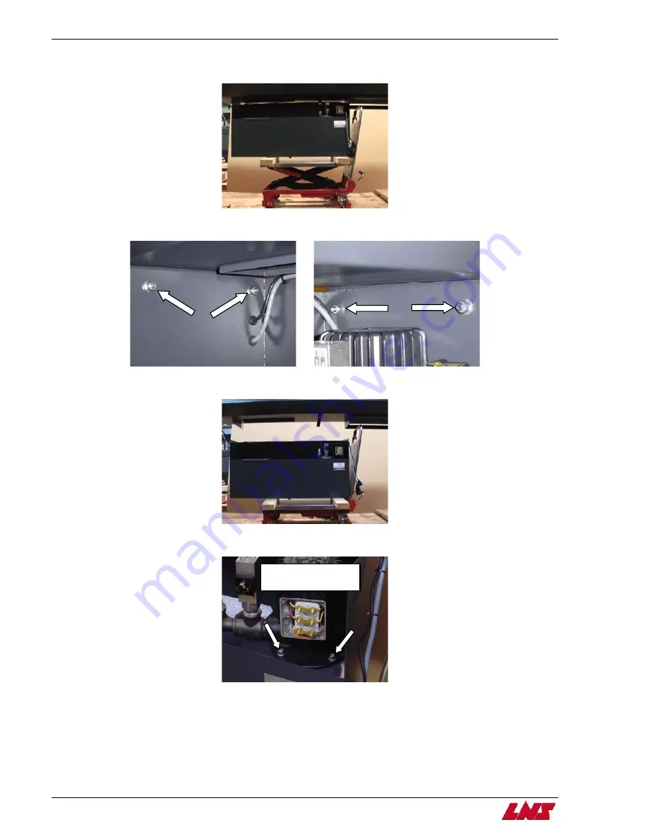
Step 4: Place the 2”x4”s on the jack and set the jack underneath the hydraulic tank. Raise the jack, so that the hydraulic tank is
sitting on the 2”x4”s.
Step 5: Remove the four tank mounting screws.
rain the cables running into the tank that are strapped to the bottom of the coffin).
Step 7: Remove the four motor mounting bolts and remove the pump motor from the tank.
Step 6: Drop the tank down. (Be careful not to st
The two bolts in the
back are not shown.
Содержание Hydrobar Express 220
Страница 61: ......
Страница 143: ......
Страница 147: ......
Страница 154: ...Chapter 6 Spare Parts Spare Parts 6 7 HYDROBAR EXPRESS 220 Chapter 6 6 7 HYDROBAR EXPRESS 220 Chain Drive Assembly L F ...
Страница 155: ...6 8 Chapter 6 Spare Parts Spare Parts HYDROBAR EXPRESS 220 6 8 Chapter 6 HYDROBAR EXPRESS 220 Chain Drive Assembly R F ...
Страница 156: ...Chapter 6 Spare Parts 6 9 HYDROBAR EXPRESS 220 Servo Motor Assembly ...
Страница 157: ...6 10 Chapter 6 Spare Parts Spare Parts HYDROBAR EXPRESS 220 6 10 Chapter 6 HYDROBAR EXPRESS 220 Remnant Vise ...
Страница 158: ...Chapter 6 Spare Parts Spare Parts 6 11 HYDROBAR EXPRESS 220 Chapter 6 6 11 HYDROBAR EXPRESS 220 Sensor Support Assembly ...
Страница 161: ...6 14 Chapter 6 Spare Parts HYDROBAR EXPRESS 220 Hydraulic Pump Assembly ...
Страница 162: ...Chapter 6 Spare Parts Spare Parts 6 15 HYDROBAR EXPRESS 220 Chapter 6 6 15 HYDROBAR EXPRESS 220 Coding Disc Assembly ...
Страница 163: ...6 16 Chapter 6 Spare Parts HYDROBAR EXPRESS 220 Diameter Adjustment Motor Assembly ...
Страница 164: ...Chapter 6 Spare Parts 6 17 HYDROBAR EXPRESS 220 Air Regulator and Cable Passage Plate ...


