Spirit II User’s Manual
Section 6: Maintenance &Troubleshooting
This information is subject to the controls of the Export Administration Regulations [EAR]. This information shall not be provided to
non-U.S. persons or transferred by any means to any location outside the United States contrary to the requirements of the EAR.
6-11
Chopper Test Procedure
WARNING: Only qualified maintenance personnel should perform the chopper
test procedure. The system utilizes potentially fatal A.C. and D.C. voltages. All
maintenance should be performed with safety in mind.
Use extreme caution when working near the power conversion module (i.e.,
chopper). The large electrolytic capacitors store large amounts of energy even
after power has been removed from the system. Wait at least five minutes after
turning off power, and then use a voltmeter to verify that the capacitors are fully
discharged before touching the power conversion module.
Capacitor failure can injure and/or cause property damage. If troubleshooting
requires the system to be powered with the enclosure panels removed, remain
clear of the capacitors. Failure of a capacitor can result in a sudden release of
stored energy causing rupture of the capacitor case.
IMPORTANT: Depending upon the system, there are one, two or three chopper
assemblies in the power supply. The following steps must be performed on each
chopper with the other chopper(s) disabled. To disable a chopper, remove the
plug from J1 on the chopper PCB (see drawing on next page).
1. Remove primary power from the Spirit system.
2. Remove the top, left, right and front covers from the power supply to expose the
DSP PCB, input and output terminal blocks and chopper(s).
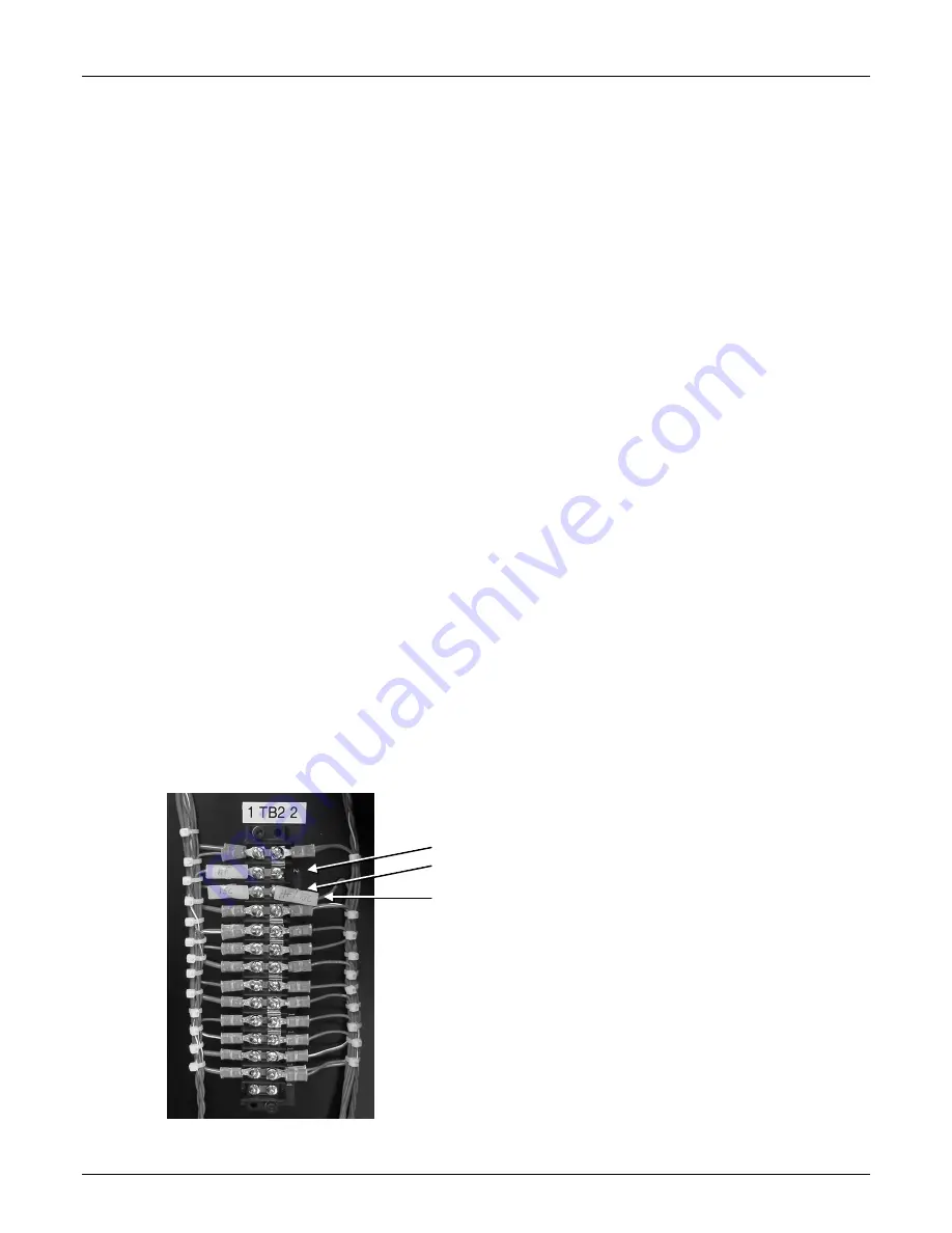
3. Remove the HF/ISC wire connected to TB2 side 2 (right side) from position 2 or 3.
Make sure to isolate the connector so that it doesn’t come in contact with anything
metal during this test. Return the jumper wire to the original position at the end of
this test.
TB2, Side 2, Position 2
TB2, Side 2, Position 3
HF/ISC Wire


