- - 7
ASSEMBLY INSTRUCTION:
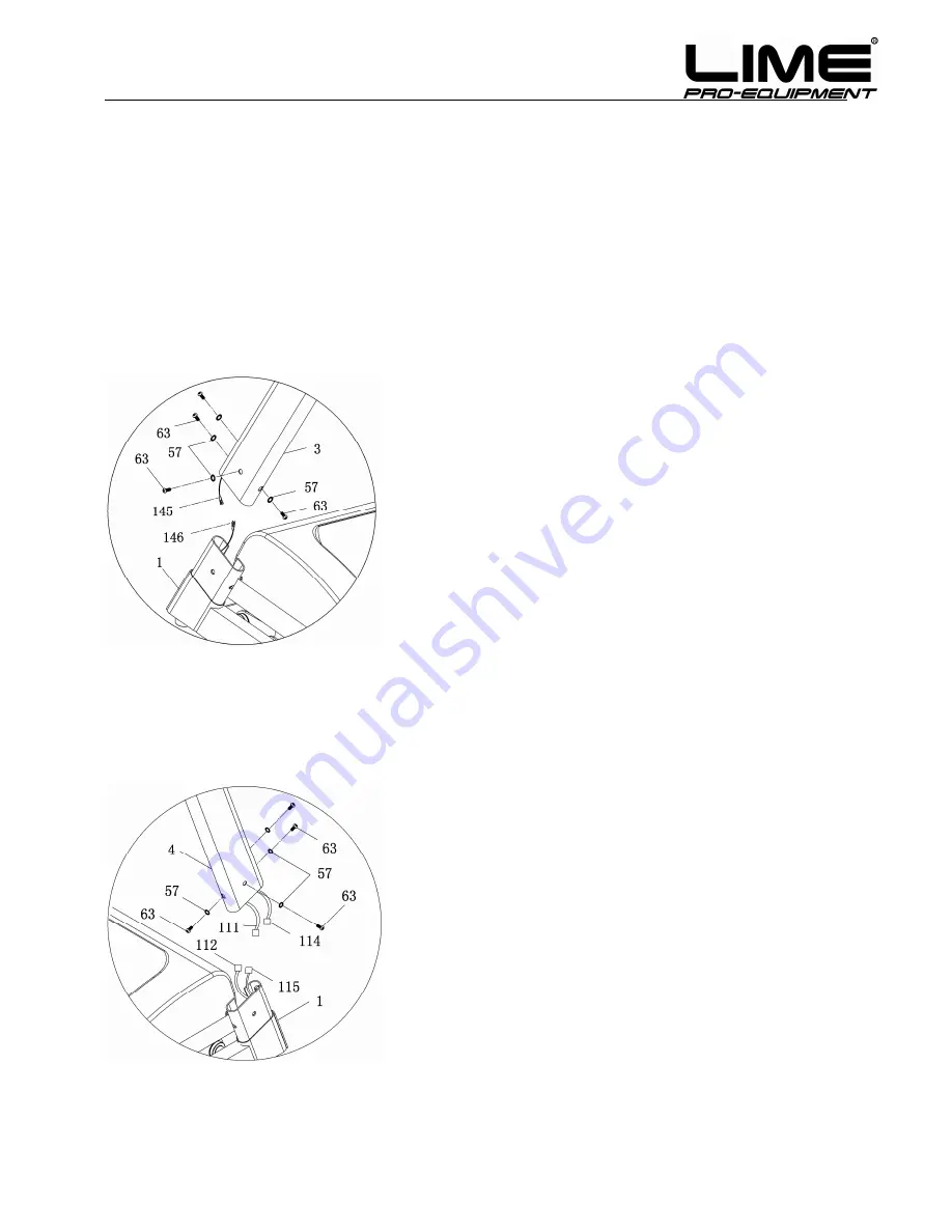
STEP 1:
STEP 2:
STEP 3:
1. Open the carton; take out the spare parts,
and put the MAIN FRAME (#1) on the ground.
4.
Connect the signal line (#111, #114) at the
end of the RIGHT UPRIGHT TUBE (#4) and
the signal line (#112, #115) at the bottom of the
MAIN FRAME (#1); then insert the RIGHT
UPRIGHT TUBE (#4) into the unit.
Notice: Don’t do assembly with strong
force, you may break the insulating layer of
the signal line, or the plug pins may be
curved, which would result in bad signal
connections.
5.
Put the BOLT (#63) and the WASHER (#57)
together, then lock the RIGHT UPRIGHT TUBE
(#4) onto the MAIN
FRAME (#1) with #6
ALLEN WRENCH.
2.
Connect the signal line (#145) at the end of the
LEFT UPRIGHT TUBE (#3) and the signal line
(#146) at the bottom of the MAIN FRAME (#1),
then insert the LEFT UPRIGHT TUBE (#3) into the
unit.
Notice: Don’t do assembly with strong force,
you may break the insulating layer of the
signal line, or the plug pins may be curved,
which would result in bad signal connections.
3.
Put the BOLT (#63) and the WASHER (#57)
together,then lock the LEFT UPRIGHT TUBE (#3)
onto the MAIN FRAME (#1) with #6 ALLEN
WRENCH.
Содержание D 11.0 Performance
Страница 1: ... 1 OWNER S MANUAL ...
Страница 26: ... 26 EXPLODED DRAWING ...


