IF51
NOTE
•
Your full scale position (final position) is allowed to be higher or lower
than the zero position (initial position).
•
Further scaling facilities and linearisation functions are available using
the PC set-up.
•
always refers to the initial output value defined by
, i.e. 0 volts or 0 mA or 4 mA.
•
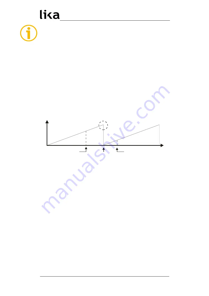
When, after setting the full scale position (final position), the yellow
status LED does not switch off, this indicates that an overflow error has
occurred, i.e. the mechanical zero position of your encoder is found
between your two teach settings (see Figure below). In this case you
need to change the zero position of the encoder (mechanically or by
programming the encoder properly). With PC set-up, the converter itself
is able to provide also an electronic suppression of the overflow jump.
•
The only way to reset an overflow error state is to switch on the power
supply.
•
The LED overflow check may fail with encoders providing a resolution
lower than 13 bits.
Encoder zero
Teach min.
Teach max.
Overflow error
7.4 SET input
Providing a HIGH signal to the SET input (DIL switch terminal 10) causes the unit
to temporary replace the SSI encoder data with the value entered next to the
register; the analogue output as well as the serial readout will
follow correspondingly. This means that independently of the actual mechanical
position of the encoder the unit internally uses the register data set in
instead of the encoder SSI data. It turns back to normal encoder reading
as soon as the SET signal goes LOW again.
This function can be very useful for testing and commissioning purposes.
The SET input uses PNP / HTL characteristics (LOW = open or 0 – 3 V, HIGH = 10
– 30 V).
MAN IF51 I_E 1.1.odt
7 - Commissioning
38 / 56


