background image

45

Model:  

CLSL (Integrity Series)

Tools Required: 

Metric Hex Key Set, Side Cutters, T-45 Torx Wrench

1.  

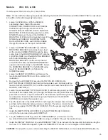
Remove the CONSOLE SUPPORT TOP CAP (a).

2.  

Remove the two SCREWS (b) securing the CONSOLE


 SUPPORT COVER (c). Remove the console 


 support  cover and set it and the screws aside.

3.  

Remove the four SCREWS (d) securing the DISPLAY  


 CONSOLE (e). Set the SCREWS aside. Tilt the    


 CONSOLE forward and disconnect all cables. Set    


 the CONSOLE aside.

4.  

Locate the TV MOUNTING BRACKET (f). With the    


 mounting holes in the tube facing downward, slide    


 the tube portion of the mounting bracket into the top of    


 the CONSOLE SUPPORT (g). Align the inserts in the  


 tube with the mounting holes on the underside of the  


 console support. Secure the mounting bracket using two   


 SCREWS (h). Tighten the screws securely.

CAUTION:   

Do not pinch any cables when inserting the    


MOUNTING BRACKET into the CONSOLE SUPPORT.

5.  

Re-install the DISPLAY CONSOLE (e) using the four  


 previously removed SCREWS (d). Tighten the SCREWS to 6-8  in-lbs. Do not overtighten the SCREWS.

CAUTION:

 Do not pinch any wires when assembling the DISPLAY CONSOLE to the console support.

6.  

Attach the ADAPTER BRACKET (i) to the ATTACHABLE TV (j) using four SCREWS (k) and WASHERS (l).    


 Tighten the SCREWS to 6-8 in-lbs. Do not overtighten the SCREWS.


 Attach the ATTACHABLE TV with ADAPTER BRACKET to the UPPER MOUNTING PLATE (m) using four  


 SCREWS (n), SHOULDER NYLON WASHERS (o) and NYLON FLAT WASHER (p). Tighten the SCREWS to 6-8   


 in-lbs. Do not overtighten the SCREWS.

7.  

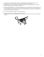
Connect the COAXIAL CABLE, POWER CORD and R    EMOTE CABLE to the rear of the ATTACHABLE TV. See    


 the 

Media Connections 

pages  in this  manual for detailed information. 

 8.   CABLE TIE (r) any excess cable together behind the ATTACHABLE TV and position the cables between the    


       MOUNTING BRACKET (f) and the DISPLAY CONSOLE (e).

9.  

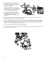
Re-install the CONSOLE SUPPORT COVER (c) and secure it 


 using the two previously removed SCREWS (b).

10.  Locate the new TOP CAP (s). Place the new top cap into 
 

 position at the top of the CONSOLE SUPPORT COVER (c). Be  sure the top cap snaps securely in place.

11.  

Secure the POWER ADAPTER (t) to the FRONT STABILIZER (u)  using two CABLE TIES (r) as shown. Be sure the    


 cable ties are pulled tight. Trim the excess cable ties. Connect the  SCREW-TYPE CONNECTOR of the 


 POWER  CORD (aa) to the front side receptacle. Bundle excess power cord and  store under the unit. Connect the 


 COAXIAL  CABLE (bb) to the broadcast supply cable in similar fashion.  

12.  Connect the POWER SUPPLY CORD to the POWER ADAPTER (t).

e

j

i

l

k

p

o

n

m

f

s

a

b

d

h

g

c

t

u

r

bb

aa

Содержание M051-00K96-0002

Страница 1: ...15 ATTACHABLE TV ASSEMBLY INSTRUCTIONS M051 00K96 0002 REV B ...

Страница 2: ...h CET Austria LIFE FITNESS Austria Vertriebs G m b H Dückegasse 7 9 3 36 1220 Vienna AUSTRIA Telephone 43 1 61 57 198 Fax 43 1 61 57 198 20 Service Email kundendienst lifefitness com Marketing Sales Email kundenberatung lifefitness com Operating Hours 08 30 16 30 h MEZ Spain LIFE FITNESS IBERIA C Frederic Mompou 5 1º1ª 08960 Sant Just Desvern Barcelona SPAIN Telephone 34 93 672 4660 Fax 34 93 672 ...

Страница 3: ...ries 25 Models 95Xi 93X 90X 27 Upright Lifecycle Exercise Bikes 29 Models 95C 97C Elevation Inspire 95C 97C Elevation Discover SI 29 Model CLSC Integrity Series 33 Models 95Ci 93C 90C 35 Recumbent Lifecycle Exercise Bikes 37 Models 95R Elevation Inspire 95R Elevation Discover SI 37 Model CLSR Integrity Series 41 Models 95Ri 93R 90R 43 Summit Trainers 45 Model CLSL Integrity Series 45 Model 95Li 46...

Страница 4: ...l interference to radio or television reception which can be determined by turning the equipment off and on the user is encouraged to try to correct the interference by one or more of the following measures Reorient or relocate the receiving antennas Increase the separation between the equipment and receiver Connect the equipment into an outlet on a circuit different from that to which the receive...

Страница 5: ... equipment by the power cord or use the cord as a handle If the electrical supply cord is damaged it must be replaced by the manufacturer an authorized service agent or a similarly qualified person to avoid a hazard Always follow the product instructions for proper operation Never insert objects into any opening of the Life Fitness product If an object should drop inside unplug this Life Fitness p...

Страница 6: ...ntation ne pas utiliser le cordon comme poignée Si le cordon d alimentation électrique est endommagé il doit être remplacé par le fabricant par un réparateur agréé ou par une personne qualifiée afin d éviter tout danger Toujours suivre les instructions sur le produit pour s assurer de son fonctionnement adéquat Ne jamais insérer aucun objet dans les ouvertures du produit Life Fitness Si un objet t...

Страница 7: ... C using one SCREW D Leave the screw loose at this time Select a user accessible location to mount the remote control Position the remote with bracket at the desired location Pivot the remote as necessary for optimal user access Note If the desired location is such that the bracket will not work for mounting remove the front bracket and reinstall the pivot disc The remote can now be installed usin...

Страница 8: ...Audio Video Connection High Definition S Video S Video Signal In S Video Video In Video In RCA yellow Audio In Stereo Line In RCA red and white RF Coaxial Antenna Cable Connection RF F Type Wired Remote Media Cable Wired Remote Control Connection Remote Control Audio Out Headphone Connection 3 5mm stereo jack 0 3W 12VDC MTI Hi Def CATV CVBS Power In MTI Network In USB Hi Def Input S Video Video In...

Страница 9: ...igh Definition VGA In PC Video Connection VGA S Video In S Video Signal In S Video Audio Out Headphone Connection 3 5mm stereo jack 0 3W Wired Remote Media Cable Wired Remote Control Connection Remote Control RF Coaxial Antenna Cable Connection RF F Type USB USB Flash Drive USB Type A Power In 12VDC Video In CVBS Audio In Right Left Hi Def High Definition Input VGA In S Video In Audio Out Wired Re...

Страница 10: ... Type A High Definition Input High Definition Audio Video Connection High Definition D SUB PC VIdeo Connection VGA Audio In Stereo Line In RCA red and white Video In Video In RCA yellow S Video In S Video Signal In S Video RF Coaxial Antenna Cable Connection RF F Type Audio Out Headphone Connection 3 5mm stereo jack 0 3W Wired Remote Media Cable Wired Remote Control Connection Remote Control Power...

Страница 11: ...ion VGA Video In Video In RCA yellow Audio In Stereo Line In RCA red and white S Video In S Video Signal In S Video RF Coaxial Antenna Cable Connection RF F Type Wired Remote Media Cable Wired Remote Control Connection Remote Control Audio Out Headphone Connection 3 5mm stereo jack 0 3W Power In 12VDC Video In CVBS Audio In Right Left Hi Def High Definition Input VGA In S Video In Audio Out Wired ...

Страница 12: ...er strip Remove the remaining protective liner from fastener strip and secure the power block to the frame as shown 1c Plug the POWER CORDS 2 leading from the motor compartment and left upright into their respective ends of the POWER BLOCK 1 Feed excess cable into the left upright 1d Re install the motor cover using the six previously removed screws 2 Attach the LOWER MOUNTING BRACKET 3 to the MAI...

Страница 13: ...tach the three MEDIA CABLES 12 to the back of the Discover SI CONSOLE C as shown below 7 Hold the MAIN BRACKET ASSEMBLY 4 close to the CONSOLE BRIDGE 13 as shown With the holes facing upward feed the taped end of the MEDIA CABLES 12 through the bottom of the main bracket assembly and out of the upper hole as shown Carefully pull excess media cable through the main bracket assembly 8 Slide one GROM...

Страница 14: ...h the back of the console Position the REMOTE BRACKET E into position replacing the BOTTOM INSERT C Secure the REMOTE BRACKET E using the previously removed SCREWS A and WASHERS B 10 With the remaining TV BRACKET 15 oriented as shown install it to the back of the ATTACHABLE TV 16 using four SCREWS 17 and WASHERS 18 Tighten the screws securely 8 10 ft lbs Note Be sure the side holes of the TV brack...

Страница 15: ...ASSEMBLY 4 14 Replace the REAR CONSOLE COVER 10 and secure it using the previously removed two SCREWS 9 Tighten the screws securely 8 10 ft lbs Do not overtighten the screws 15 Slide the BRACKET COVER 7 down to meet the REAR CONSOLE COVER 10 Snap the BRACKET COVER into the REAR CONSOLE COVER 16 Align the lowest side holes on the TV BRACKETS 8 15 Secure the TV BRACKET into proper position using one...

Страница 16: ...CKET TUBE g and exiting through the CENTER HOLE a4 of the TV MOUNTING BRACKET TUBE g Install a GROMMET a5 onto the CENTER HOLE a4 3 If through holes in the four CONSOLE BOSSES d are not present use a 5 16 drill from the top center of the four console bosses to create through holes Note Be careful not to damage the threads of the brass inserts when drilling the through holes in the console bosses d...

Страница 17: ...ontrol board using DOUBLE SIDED TAPE Connect the SCREW TYPE CONNECTOR u of the POWER ADAPTER to the pre wired TV POWER CABLE v Bundle excess power cord and store inside the left upright Connect the POWER SUPPLY CORD c to the POWER ADAPTER r 10 Replace the motor shroud using the screws provided 11 Connect the COAXIAL CABLE c to the broadcast supply in a similar fashion Note Be sure to leave 12 of e...

Страница 18: ...LEBAR 1 Secure the REMOTE CABLE using two CABLE TIES j at the locations shown Be sure the cable ties are pulled tight and trim the excess cable ties Route the remaining REMOTE CABLE through the CABLE CLIP k located on the bottom left of the REAR CONSOLE c and up through the left access panel Route the REMOTE CABLE through the LARGE CABLE CLIP f located at the center inside of the rear console Cont...

Страница 19: ...ing nut previously removed Tighten the nut securely Attach the COAXIAL CABLE e leading from the left upright to the top of the coupler Attach the broadcast SUPPLY CABLE z to the bottom of the coupler Note Be sure to leave at least 12 of excess broadcast SUPPLY CABLE z between the floor and the coaxial connection on the unit to accommodate elevation of the unit 14 Remove the RETAINING NUT aa and WA...

Страница 20: ...hten the screws securely Note ALL CABLES should be routed through the CABLE GUIDE c located at the lower left of the REAR CONSOLE R 5 If through holes in the four CONSOLE BOSSES g are not present use a 5 16 drill from the top center of the four console bosses to create through holes Note Be careful not to damage the threads of the brass inserts when drilling the through holes in the console bosses...

Страница 21: ...eceptacle Bundle excess power cord and store under the unit Connect the COAXIAL CABLE v to the broadcast supply cable in similar fashion Note Be sure the POWER ADAPTER r and CABLE TIES t do not interfere with the lift mechanism Note Be sure to leave at least 12 of excess coaxial cable between the floor and the coaxial connection on the unit to accommodate elevation of the unit 11 Connect the power...

Страница 22: ...lock to the underside of the CENTER FRAME as shown Connect the SCREW TYPE CONNECTOR of the POWER CORD 2 to the underside receptacle Bundle excess power cord and store under the unit Connect the COAXIAL CABLE 3 to the broadcast supply receptacle in similar fashion b Connect the POWER CORD 2 to the POWER BLOCK 1 1 Attach the TV BRACKET with bent tab 4 to the MAIN BRACKET 5 as shown using four SCREWS...

Страница 23: ...KET ASSEMBLY 5 close to the CONSOLE BRIDGE 13 as shown With the holes facing upward feed the taped end of the MEDIA CABLES 12 through the bottom large hole of the main bracket assembly and out of the upper hole as shown Carefully pull excess media cable through the main bracket assembly 7 Slide the remaining GROMMET 16 over the taped end of the MEDIA CABLES 12 Install the grommets into the access ...

Страница 24: ...oles facing upward feed the taped end of the MEDIA CABLES 12 through the bottom large hole of the main bracket assembly and out of the upper hole as shown Carefully pull excess media cable through the main bracket assembly 7 Slide the remaining GROMMET 16 over the taped end of the MEDIA CABLES 12 Install the grommets into the access holes 8 Install the MAIN BRACKET CAPS 19 to the top and bottom of...

Страница 25: ... manual for detailed information 15 Align the lowest side holes on the TV BRACKETS 4 20 Secure the TV bracket into proper position using one SCREW 27 on each side 16 Plug in and power on the TV Refer to the ATTACHABLE TV Operation Manual for proper TV setup For Achieve Console Units Only a Remove the two SCREWS A and WASHERS B securing the BOTTOM INSERT C Remove the BOTTOM INSERT Do not discard th...

Страница 26: ...les through the OPENING f of the TV MOUNTING BRACKET g 3 Locate the AUDIO VIDEO I R REMOTE CONTROL CABLE h Route this CABLE ASSEMBLY through the TV MOUNTING BRACKET with the 2 connector end coming out the OPENING f of the TV MOUNTING BRACKET g 4 Secure the TV MOUNTING BRACKET g with four SOCKET HEAD SCREWS s onto the CONSOLE SUPPORT TUBE c CAUTION Do not pinch any cables when inserting the TV MOUN...

Страница 27: ...P o Place the new top cap into position at the top of the TV MOUNTING BRACKET g Be sure the top cap snaps securely in place 11 Secure the POWER ADAPTER p to the FRONT STABILIZ ER q using two CABLE TIES r as shown Be sure the cable ties are pulled tight Trim the excess cable ties Connect the SCREW TYPE CONNECTOR of the power SUPPLY CORD d to the underside receptacle Bundle any excess POWER SUPPLY C...

Страница 28: ...he MONOCOLUMN H and up through the top of the CONSOLE SUPPORT 7 alongside the power cord and coaxial cable 7 Locate the MOUNTING BRACKET e With the mounting holes in the tube facing downward slide the tube portion of the mounting bracket into the top of the CONSOLE SUPPORT 7 Align the inserts in the tube with the mounting holes on the underside of the console support Secure the mounting bracket us...

Страница 29: ...ition at the top of the CONSOLE SUPPORT COVER 8 Be sure the top cap snaps securely in place 15 Secure the POWER ADAPTER o to the FRONT STABILIZER p using two CABLE TIES m as shown Be sure the cable ties are pulled tight and trim the excess cable ties Connect the SCREW TYPE CONNECTOR of the POWER CORD q to the under side receptacle Bundle excess power cord and store under the unit Connect the COAXI...

Страница 30: ...stener strip and secure the power block to the underside of the center frame as shown Connect the SCREW TYPE CONNECTOR of the POWER CORD 2 to the underside receptacle Bundle excess power cord and store under the unit Connect the COAXIAL CABLE 3 to the broadcast supply receptacle in similar fashion b Connect the POWER SUPPLY CORD to the POWER BLOCK 1 1 Attach the TV BRACKET with bent tab 4 to the M...

Страница 31: ...o the CONSOLE BRACKET 15 as shown With the holes facing upward feed the taped end of the MEDIA CABLES 12 through the bottom large hole of the main bracket assembly and out of the upper hole as shown Carefully pull excess media cable through the main bracket assembly 7 Slide the remaining GROMMET 16 over the taped end of the MEDIA CABLES 12 Install the grommets into the access holes 8 Install the M...

Страница 32: ...oles facing upward feed the taped end of the MEDIA CABLES 12 through the bottom large hole of the main bracket assembly and out of the upper hole as shown Carefully pull excess media cable through the main bracket assembly 7 Slide the remaining GROMMET 16 over the taped end of the MEDIA CABLES 12 Install the grommets into the access holes 8 Install the MAIN BRACKET CAPS 19 to the top and bottom of...

Страница 33: ... excess media cable into the MAIN BRACKET 5 15 Align the lowest side holes on the TV BRACKETS 4 20 Secure the TV BRACKET into proper position using one SCREW 27 on each side 16 Plug in and power on the TV Refer to the ATTACHABLE TV Operation Manual for proper TV setup For Achieve Console Units Only a Remove the two SCREWS A and WASHERS B securing the BOTTOM INSERT C Remove the BOTTOM INSERT Do not...

Страница 34: ... CORD cc and COAXIAL CABLE dd located within the CONSOLE SUPPORT BRACKET TUBE c Route these cables through the opening of the TV MOUNTING BRACKET e Locate the AUDIO VIDEO I R CABLE ASSEMBLY f Route this cable assembly through the TV MOUNTING BRACKET e with the 2 connector end coming out of the opening of the TV MOUNTING BRACKET 4 Insert the TV MOUNTING BRACKET into the CONSOLE SUPPORT TUBE and fas...

Страница 35: ... lbs Connect the COAXIAL CABLE POWER CORD and AUDIO VIDEO I R CABLE ASSEMBLY to the rear of the ATTACHABLE TV See the Media Connections pages in this manual for detailed information 10 Re insert the previously removed square END CAP a into the top of the TV MOUNTING BRACKET 11 Secure the POWER ADAPTER x to the FRONT STABILIZER y using two CABLE TIES z as shown Be sure the CABLE TIES are pulled tig...

Страница 36: ...allation 4 Remove the four SCREWS 2 securing the TOP POLAR COVER to the BOTTOM POLAR COVER 6 and remove the top polar cover Carefully pull the lead end of each CABLE TIE C V until the receptor end meets the bottom of the REMOTE CONTROL e 5 Locate the provided NEW TOP POLAR COVER f with mounting slots Feed both lead ends of the CABLE TIES C V through the bottom mounting slots of the top polar cover...

Страница 37: ...he ATTACHABLE TV k and position the cables between the MOUNTING BRACKET b and the DISPLAY CONSOLE 4 13 Secure the POWER ADAPTER p to the FRONT STABILIZER q using two CABLE TIES j as shown Be sure the cable ties are pulled tight and trim the excess cable ties Connect the SCREW TYPE CONNECTOR of the POWER CORD r to the underside receptacle Bundle excess power cord and store under the unit Connect th...

Страница 38: ...ener strip and secure the power block to the underside of the center frame as shown Connect the SCREW TYPE CONNECTOR of the POWER CORD 2 to the underside receptacle Bundle excess power cord and store under the unit Connect the COAXIAL CABLE 3 to the broadcast supply receptacle in similar fashion b Connect the POWER CORD to the POWER BLOCK 1 1 Attach the TV BRACKET with bent tab 4 to the MAIN BRACK...

Страница 39: ...KET ASSEMBLY 5 close to the CONSOLE BRACKET 15 as shown With the holes facing upward feed the taped end of the MEDIA CABLES 12 through the bottom large hole of the main bracket assembly and out of the upper hole as shown Carefully pull excess media cable through the main bracket assembly 7 Slide the remaining GROMMET 16 over the taped end of the MEDIA CABLES 12 Install the grommets into the access...

Страница 40: ...s facing upward feed the taped end of the MEDIA CABLES 12 through the bottom large hole of the main bracket assembly and out of the upper hole as shown Carefully pull excess media cable through the main bracket assembly 7 Slide the remaining GROMMET 16 over the taped end of the MEDIA CABLES 12 Install the grommets into the access holes 8 Install the MAIN BRACKET CAPS 19 to the top and bottom of th...

Страница 41: ... excess media cable into the MAIN BRACKET 5 15 Align the lowest side holes on the TV BRACKETS 4 20 Secure the TV BRACKET into proper position using one SCREW 27 on each side 16 Plug in and power on the TV Refer to the ATTACHABLE TV Operation Manual for proper TV setup For Achieve Console Units Only a Remove the two SCREWS A and WASHERS B securing the BOTTOM INSERT C Remove the BOTTOM INSERT Do not...

Страница 42: ...CORD cc and COAXIAL CABLE dd located within the CONSOLE SUPPORT BRACKET TUBE c Route these cables through the opening of the TV MOUNTING BRACKET e Locate the AUDIO VIDEO I R REMOTE CONTROL CABLE ASSEMBLY f Route this cable assembly through the TV MOUNTING BRACKET e with the 2 connector end coming out of the opening of the TV MOUNTING BRACKET 4 Insert the TV MOUNTING BRACKET into the CONSOLE SUPPOR...

Страница 43: ...s Connect the COAXIAL CABLE POWER CORD and AUDIO S VIDEO I R REMOTE CONTROL CABLE ASSEMBLY to the rear of the ATTACHABLE TV See the Media Connections pages in this manual for detailed information 10 Re insert the previously removed square END CAP a into the top of the TV MOUNTING BRACKET 11 Secure the POWER ADAPTER x to the FRONT STABILIZER y using two CABLE TIES z as shown Be sure the CABLE TIES ...

Страница 44: ...ide the MOUNTING BRACKET upward until it locks solidly in the SPACER Secure the MOUNTING BRACKET to the SPACER using two FLAT HEAD SCREWS e Tighten the SCREWS securely 3 Locate the REMOTE CONTROL f Configure the remote control for a vertical c V installation Secure the REMOTE CONTROL to the top of the HANDLEBAR g as shown Be sure the CABLE TIES c v are pulled tight and trim the excess cable ties 4...

Страница 45: ...RONT STABILIZER q using two CABLE TIES j as shown Be sure the cable ties are pulled tight and trim the excess cable ties Connect the SCREW TYPE CONNECTOR of the POWER CORD r to the underside receptacle Bundle excess power cord and store under the unit Connect the COAXIAL CABLE s to the broadcast supply receptacle in similar fashion 10 Connect the POWER SUPPLY CORD to the POWER ADAPTER p 11 Continu...

Страница 46: ...V j using four SCREWS k and WASHERS l Tighten the SCREWS to 6 8 in lbs Do not overtighten the SCREWS Attach the ATTACHABLE TV with ADAPTER BRACKET to the UPPER MOUNTING PLATE m using four SCREWS n SHOULDER NYLON WASHERS o and NYLON FLAT WASHER p Tighten the SCREWS to 6 8 in lbs Do not overtighten the SCREWS 7 Connect the COAXIAL CABLE POWER CORD and REMOTE CABLE to the rear of the ATTACHABLE TV Se...

Страница 47: ...ocate the TV MOUNTING BRACKET o With the mounting holes in the tube facing downward slide the tube portion of the mounting bracket into the top of the CONSOLE SUPPORT n Align the inserts in the tube with the mounting holes on the underside of the console support Secure the mounting bracket using two SCREWS p Tighten the screws securely CAUTION Do not pinch any cables when inserting the mounting br...

Страница 48: ...2 Locate the new TOP CAP x Place the new top cap into position at the top of the CONSOLE SUPPORT COVER c Be sure the top cap snaps securely in place 13 Secure the POWER ADAPTER y to the FRONT STABILIZER z using two CABLE TIES w as shown Be sure the cable ties are pulled tight and trim the excess cable ties Connect the SCREW TYPE CONNECTOR of the POWER CORD aa to the front side receptacle Bundle ex...

Страница 49: ...R SUPPLY CORD cc and COAXIAL CABLE dd located within the CONSOLE SUPPORT BRACKET TUBE c Route these cables through the opening of the TV MOUNTING BRACKET e Locate the AUDIO VIDEO I R REMOTE CONTROL CABLE ASSEMBLY f Route this cable assembly through the TV MOUNTING BRACKET e with the 2 connector end coming out of the opening of the TV MOUNT ING BRACKET 4 Insert the TV MOUNTING BRACKET into the CONS...

Страница 50: ... 9 Reattach the console to the console support bracket with the four previously removed screws in Step 2 Connect the COAXIAL CABLE POWER CORD and AUDIO VIDEO I R REMOTE CONTROL CABLE ASSEMBLY to the rear of the ATTACHABLE TV See the Media Connections pages in this manual for detailed information 10 Re insert the previously removed square END CAP a into the top of the TV MOUNTING BRACKET 11 Secure ...

Страница 51: ... the power cord and coaxial cable through the channel at the top of the SPACER 4 Locate the MOUNTING BRACKET e With the MOUNTING BRACKET oriented as shown feed all the console CONNECTORS through the large center hole in the MOUNTING BRACKET Align the LOCATING TABS f of the MOUNTING BRACKET with the tab slots and position the MOUNTING BRACKET into the center channel of the SPACER d Slide the MOUNTI...

Страница 52: ...IZER o using two CABLE TIES c as shown Be sure the cable ties are pulled tight and trim the excess cable ties Connect the screw type connector of the POWER CORD p to the underside receptacle Bundle excess power cord and store under the unit Connect the coaxial cable q to the broadcast supply cable in similar fashion 10 Connect the POWER SUPPLY CORD to the POWER ADAPTER n 11 Continue with the remai...

Отзывы: