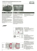
Electric locomotive
coupling
For those who have put this theory into practise,
many will have undoubtedly come into conflict
with the locomotive coupling, with the exception
of those LGB enthusiasts who have already
converted their vehicles with the new symetric
couplings (Spare parts No.
2040/2).
The fact, that
one is forced to place the electric locomotive onto
the tracks in a definite position, determines
at
wh ich end the coupling will be and naturally also
the locomotive position with respect to the
direction of travel. Please note, in our circuit plans
the locomotive coupling is always shown pointing
to the right.
Naturally
,
one of the most common mistakes
wh ich is made with this system, is to think that by
reversing the locomotive position on the tracks
(coupling to the left) the problem can be solved. In
this case however, the locomotive will not be
supplied with voltage from the pantograph,
apart
from this, the diesellocomotive
will be influenced
by the overhead line supply controller so that it
will drive in an uncontrolled
manner.
Fig. 2
If one wishes to reverse the "main driving
direction" of the locomotive, then one should
drive with the coupling to the front. This is not
abnormal, as when shunting or when reversing
the driving direction, e
.
g
.
at the termini, this
locomotive, waggon combihation
is perfectly
normal.
You may put diesel and steam locos onto the
track as you want.
Tips and Tricks - Switched section and
control rail
For overhead operation, we differentiate between
traction tyre rail and return rail. For sidings,
switched sections and disconnecting
tracks, for
signals with train control, only the return rail will
be disconnected
via the Disconnecting
Track
1015U or Isolating Track Connectors 5026. For
this reason, the return rail can be described as the
control rail.
Fig
.
5
By means of track switching in the control
rail, e
.
g
.
signal with train control, an electric
locomotive being driven from overhead lines can
be controlled
.
No extra control switching is
required for the overhead line
.
Those who follow
this rule will have no difficulties when making
subsequent
changes for overhE(ad operation
.
Tips and Tricks - Interconnecting
To simplify the wiring, the double connection to
the common return rail, can be replaced with a
short interconnecting
lead between the individual
controllers.
Circuit splitting for three train operation
Fig.3
This is an example of a universal
overhead line for two separate circuits.
The interruption in the circuit is only carried out in
the positive rail by means of the Isolating Track
Connectors 5026 or Disconnecting
Track
1015 U. The return rail and overhead lines are not
interrupted. The blue negative connections
of all
controllers are linked together by means of short
interconnecting
leads and then connected by
means of a single lead to the return rail.
When running from Circuit 1 to Circuit 2, it should
be observed, that the controller knobs are in the
same position
.
Circuit splitting for four train operation
Fig
.
6
Interruption in the circuits is carried out in
both rails by means of the Isolating Track
Connectors 5026 or with a Disconnecting
Track
1015 T. The overhead line circuit however, is not
interrupted.
This style of connecting can be complemented
on
other circuits. The red connections
of all catenary
system controllers should be linked together and
then connected to the overhead line circuit which
is not interrupted.
2
Due to the fact, that the overhead lines form an
interconnected
closed circuit, the tracks of
different circuits can be crossed without problems
by using the Crossings 1300 or 1320.
At
the same
time, the overhead lines of the catenary system
wh ich cross one another, need not to be insulated
or interrupted.
It should be noted, that the LGB
Model Catenary System al$o allows the
overhead lines to be interrupted for special circuit
connecting.
- Page 4 -
Electric Locomotive
2030
Type Bo
2030 Original
On the south-bound
stretch of the ÖBB,
Bruck-Graz, the branch line track, Mixnitz-St. Er-
hard (LB.M
-
StE
.
)
begins
.
The section is only
10.4 km long, built in gauge 760 mm, was
electrified right from the start: this was, to say the
least, for those days, a very progressive decision
for the founder
.
In this picturesque
landscape, the stretch of
tracks takes us in the region, near to the
Bärenschützklamm,
to the terminus in St. Erhard.
Right from the start, in 1913, two short electric
locomotives of the type Bo were put into service
.
They pulled passenger and freight trains, mostly
in mixed combinations
.
Today this railway is mainly used to cärry freight
forthe Magnesitwerkes
in St. Jakob. Both original
locomotives are still in service today. The original
Iyre type overhead collectors have been replaced
with modern pantographs.
Technical
Data:
Fig
.
1
-
3
Our originallocomotive
E 1 with the old
locomotive designation
"BREITENAU"
was built
by the AEG in 1913, with the Serial No
.
1508.
Gauge 760 mm. Single axle drive. Weight
15 tons. Branch-line,
between buffer coupling.
Max. speed 30 km/h
o
Length incl. buffers 5.09 m.
2030 Model
With its white-blue livery and red pantograph
current collector for overhead traction, this small
locomotive is not only a charming ornament for
every LGB layout, but also has a number of
specialities
:
Both driver's cab doors can be
opened and are fitted with automatic closing
mechanisms.
Through the open dOors, one gets
a view of the completely designed driver's stand
.
It speaks for itself, that both headlights on either
end, light up depending upon the direction of
travel.
Overaillength
245 mm.
Selector switch for "Type of traction"
Fig.3
The selector switch for rail or overhead
traction is fitted on the left-hand side of the
driver's cab (see also Page 2).
1: Overhead traction with lighting
0: Off position for parking
,
lighting and tractioh
dead.
2: Rail traction with lighting (Set to this position
before leaving the factory).
Replacing the lighting bulbs
Fig
.
4
Unscrew the four screws (1 and 2),
remove the upper part (3), remove the printed
circuit, by tilting (4), unplug the bulb (5).
Gearbox
Fig
.
4
Unscrew the 4 screws (1 and 2), remove
upper housing (3), remove gearbox from frame
(6).
When reassembling,
take care that the "Red
spots" on the gearbox match one another, (see
Page 2).
Spare parts:
2120
Carbon brushes
2218
Contact shoe with spring
2030/5 Complete motor-block
5051/1 Micro-bulb 5 V, 33 mA.
LGB-Branch
line romanticism
under
overhead lines
Fig. 5
Locomotive E 1 on a natural hilly section.
Fig. 6
Branch line station with railcar service.
- Page 5 -
Tramcars 2035 - 3500
2035
'
3500 Original Trams
Built by Siemens at the turn of the century, this
open platform, double-axle tram, was used in
various similar designs for a long time in many
large and small cities and towns throughout
Europe
.
For instance, they were in service in
Darmstadt as late as 1965 and then as
maintenance wagon
.
The significance of the
tramways, lies not only in inner city transport but
also for overland stretches where they were
frequently used. These charcteristic
branch lines
were also frequently used for freight trains.
2035 Model
Tramcar driver with magnetic base for mounting
on both platforms.
Complete interior furnishings,
long side seats for
passengers.
Detailed reproduction of the driver's
cab with moveable driving and brake levers,
formed points setting lever
,
turnable route names
and tram numbers, advertisement
boards,
various coloured city coats of arms for individual
selection, standard internallighting
and
headlights which autochange according to the
direction of travel, selection switch for type of
operation in passenger compartment.
Length
260 mm.
LGB-Accessories
for tramcars
Fig. 1
On an LGB-Modell Railway Layout, a
tramcar is a welcome extra, especially as
tramcars are often used in overland lines
.
a) LGB-Platform
5034
For levelling LGB-Tracks on single and
multi-track stations and stopping islands
.
b) LGB-Advertising
pillar 5038
c) LGB-Stopping
Point Set 5033
d) LGB-Street Lantern 5050
An LGB- Tramcar with trailer
can be colourfully decorated to meet the wildest
dreams. An enclosed set of designating labels
contains all that is required for a fully authentic
tramcar operation, e. g. Route numbers,
stopping-point
names for the rotating route-
boards, red-white striped warning signs for
service vehicles and numerous European city
coats of arms.
As the Tramcar Companies who operate urban
traffic rent advertising
·
space on their vehicles, we
supply a set of designating labels forthis purpose.
This set of advertising labels can be separately
ordered under the Order No. 2035/5.
Tramcar trailer 3500
Construction
as for the tramcar, with internal
lighting.
'
The voltage supply for the LGB- Tramcar Trailer is
supplied from the tramcar, original true. For this
reason, LGB-Tramcars
are fitted with lighting
sockets with imitation lighting leads
.
These
sockets enable a number of trailers to be supplied
through the enclosed interconnecting
leads.


