


3-3
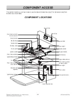
COMPONENT ACCESS
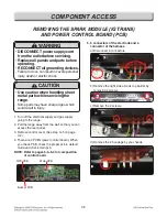
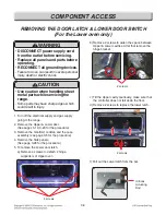
REMOVING THE SPARK MODULE (IG TRANS)
AND POwER CONTROL BOARD (PCB)
1. Turn off the electrical supply and gas supply
going to the range.
2. Pull the range away from the wall so that you can
access the rear panel.
3. Remove control cover (See step 3~5 on page
3-2)
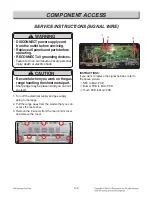
4. There are 3 PCB's (power control board). When
you check PCB, check the proper pcb in default
mode and check main pcb.
NOTE: Refer to pages 6-2~6-4 for composition
of control board
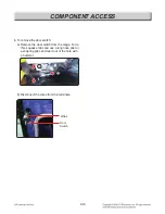
5. 5 connectors of the electrode and a
connector of the harness.
a) Disconnect 6 connectors.
b) Remove the right side of cook top barrier by
removing 2 screws.
c) Remove the 2 screws.
d) Remove the 2 housings by your hands.
Buzzer PCB
NFC PCB
Main PCB
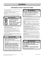
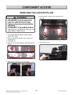
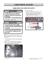
WARNING
• DISCONNECT power supply cord
from the outlet before servicing.
• Replace all panels and parts before
operating.
• RECONNECT all grounding devices.
- Failure to do so can result in severe personal
injury, death or electric shock.
CAUTION
• Use caution when handling sheet
metal parts while servicing the
range.
- Some parts may have sharp edges, which
could result in injury.
Содержание LDG4313BD
Страница 50: ...6 1 Composition of control 1 Wiring Diagram Main system PCB ...
Страница 53: ...6 4 Composition of control NFC PCB P N EBR78789101 Buzzer PCB EBR76332902 ...
Страница 93: ......


