background image

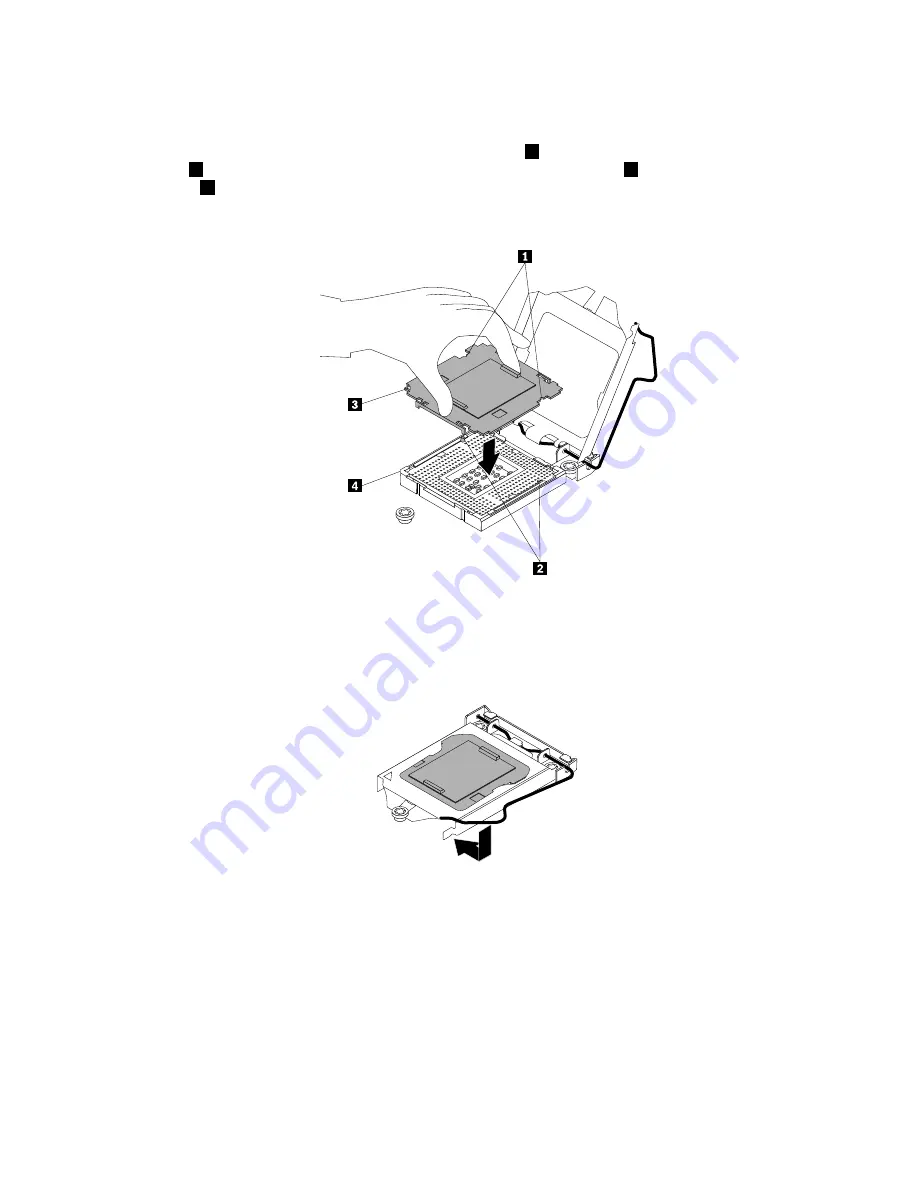
To install a microprocessor socket cover on the old system board, do the following:

a. Ensure that the small handle and the microprocessor retainer are in the fully open position. Hold the

microprocessor socket cover and align the small triangle

3

on the socket cover with the beveled

corner

4

on the microprocessor socket. You also can align the notches

1

on the socket cover with

the tabs

2

in the microprocessor socket. Then, lower the socket cover into the socket and carefully

press the socket cover until it snaps into position.

Figure 117. Installing the microprocessor socket cover

b. Gently close the microprocessor retainer, press down the small handle, and then push the handle

inward to lock the retainer into position and secure the microprocessor socket cover in the socket.

Figure 118. Securing the microprocessor socket cover

14. Install all parts that you have removed and connect all cables to the new system board. Refer to

the information that you have recorded and the related topics in “Installing, removing, or replacing
hardware” on page 74.

15. If you are instructed to return the old system board, follow all packaging instructions and use any

packaging materials that are supplied to you for shipping.

What to do next:

• To work with another piece of hardware, go to the appropriate section.

162

ThinkServer TS440 Hardware Maintenance Manual

Содержание ThinkServer TS440 70AL

Страница 1: ...ThinkServer TS440 Hardware Maintenance Manual Machine Types 70AL 70AM 70AN and 70AQ ...

Страница 2: ...ur product Safety information on page iii Appendix A Notices on page 177 Third Edition May 2014 Copyright Lenovo 2013 2014 LIMITED AND RESTRICTED RIGHTS NOTICE If data or software is delivered pursuant a General Services Administration GSA contract use reproduction or disclosure is subject to restrictions set forth in Contract No GS 35F 05925 ...

Страница 3: ...es of the ThinkServer EasyStartup program 54 Starting the ThinkServer EasyStartup program 55 Using the ThinkServer EasyStartup program on a Windows operating system 56 Configuring RAID 57 About RAID 57 RAID for your server 58 Configuring the system BIOS to enable onboard SATA RAID functionality 59 Configuring the advanced SATA or SAS hardware RAID 61 Configuring the Ethernet controllers 62 Updatin...

Страница 4: ... Optical drive problems 169 Hard disk drive problems 170 Memory module problems 171 Keyboard mouse or USB device problems 172 Chapter 8 Getting information help and service 173 Information resources 173 Using the documentation 173 ThinkServer Web site 173 Lenovo Support Web site 173 Help and service 174 Before you call 174 Calling for service 174 Using other services 175 Purchasing additional serv...

Страница 5: ...n käyttöä Avant d utiliser le produit veillez à bien lire et comprendre les instructions de sécurité multilingues figurant sur le DVD de documentation fourni avec le produit Πριν χρησιμοποιήσετε το προϊόν βεβαιωθείτε ότι έχετε διαβάσει και κατανοήσει τις οδηγίες ασφάλειας οι οποίες είναι διαθέσιμες σε διάφορες γλώσσες στο DVD τεκμηρίωσης που συνοδεύει το προϊόν Vor Verwendung des Produkts sollten ...

Страница 6: ... dodanom s produktom Preden začnete uporabljati izdelek je pomembno da preberete in razumete večjezična varnostna navodila na DVD ju z dokumentacijo ki ste ga prejeli skupaj z izdelkom Antes de utilizar el producto asegúrese de leer y comprender las instrucciones de seguridad multilingües del DVD de documentación que se proporciona con el producto Var noga med att läsa säkerhetsinstruktionerna på ...

Страница 7: ... instructed otherwise in the installation and configuration procedures Connect and disconnect cables as described in the following table when installing moving or opening covers on this product or attached devices To connect To disconnect 1 Turn everything OFF 2 First attach all cables to devices 3 Attach signal cables to connectors 4 Attach power cords to outlets 5 Turn devices ON 1 Turn everythi...

Страница 8: ...A or Class 3B laser diode Note the following Laser radiation when open Do not stare into the beam do not view directly with optical instruments and avoid direct exposure to the beam Statement 4 18 kg 39 7 lb 32 kg 70 5 lb 55 kg 121 2 lb 32 kg 70 5 lb 55 kg 121 2 lb 100 kg 220 5 lb CAUTION Use safe practices when lifting Statement 5 CAUTION The power control button on the device and the power switc...

Страница 9: ...s will not support the weight of the device Statement 8 CAUTION Never remove the cover on a power supply or any part that has the following label attached Hazardous voltage current and energy levels are present inside any component that has this label attached There are no serviceable parts inside these components If you suspect a problem with one of these parts contact a service technician Statem...

Страница 10: ...s extended on the rails Statement 14 CAUTION Some accessory or option board outputs exceed Class 2 or limited power source limits You must install the appropriate interconnecting cabling in accordance with your local electrical code requirements Statement 15 CAUTION The power control button on the device may put the device in standby mode instead of turning off the device In addition the device mi...

Страница 11: ... V direct current The branch circuit overcurrent protection must be rated in accordance with local electrical code requirements Use 1 3 mm2 or 16 American Wire Gauge AWG copper conductor only not exceeding 3 meters in length Torque the wiring terminal screws to 1 4 newton meters or 12 inch pounds Provide a readily available approved and rated disconnect device in the field wiring Statement 17 CAUT...

Страница 12: ...structed by local regulations Products that are not assessed Typical products that are not assessed include but not limited to the following Server and IT rack components for example uninterruptible power supplies and current distribution systems Devices in IT rooms for example bulk storage units and network products Industrial low voltage switchgear x ThinkServer TS440 Hardware Maintenance Manual...

Страница 13: ...VD that comes with your server A printable generic version of the latest LLW also is available in more than 30 languages at http www lenovo com warranty llw_02 If you cannot obtain the LLW through the documentation DVD or Lenovo Web site contact your local Lenovo office or reseller to obtain a printed version of the LLW free of charge For warranty service consult the worldwide Lenovo Support telep...

Страница 14: ...s on how to obtain all the documentation Printed documents The following document is printed out and contained in your server package Read Me First This is a multilingual document you should read first This document guides you to read the complete warranty support and safety information on the documentation DVD that comes with your server before using the product This document also provides inform...

Страница 15: ...ument provides detailed information to help you get familiar with your server and help you use configure and maintain your server MegaRAID SAS Software User Guide This document provides information about Redundant Array of Independent Disks RAID and how to use the utility programs to configure monitor and maintain your server RAID and related devices This document is in English only Note Refer to ...

Страница 16: ...4 ThinkServer TS440 Hardware Maintenance Manual ...

Страница 17: ...s to the server See Rear view of the server on page 17 to locate the connectors 4 Turn on the server to verify operation See Turning on the server on page 45 5 Review the Unified Extensible Firmware Interface UEFI Basic Input Output System BIOS settings and customize as needed See Using the Setup Utility program on page 47 6 Configure RAID and install the operating system and basic drivers See Usi...

Страница 18: ...6 ThinkServer TS440 Hardware Maintenance Manual ...

Страница 19: ... DVD and software media Note Depending on the model your server might look slightly different from the illustration in this topic Figure 1 Server package 1 Server 2 Material box including power cords printed documentation a documentation DVD and software media Features This topic provides general information about the server features for various models Depending on your specific model some feature...

Страница 20: ...ata The internal drives supported by your server vary by model Hard disk drive Five to eight 3 5 inch hot swap Serial Advanced Technology Attachment SATA or Serial Attached SCSI SAS hard disk drives SCSI is the acronym for Small Computer System Interface Up to eight 2 5 inch hot swap SAS hard disk drives Up to four 3 5 inch hot swap SATA or SAS hard disk drives Up to four 2 5 inch SATA solid state...

Страница 21: ...ial connector on the rear panel For the location information about the connectors refer to the related topics in Locations on page 12 Ethernet connectivity The server comes with an integrated Intel Gigabit Ethernet controller as well as an Ethernet physical layer PHY of the Open Systems Interconnection model OSI model They provide the server with the ability to support the Ethernet connector on th...

Страница 22: ...r computers load an operating system or deploy executable images from a remote server by using a network interface The operation can be done independently of local data storage devices such as hard disk drives or installed operating systems Redundant Array of Independent Disks RAID Your server supports onboard SATA software RAID If a required RAID card is installed your server also supports advanc...

Страница 23: ... about the software programs that you can use to set up use and maintain the server ThinkServer EasyStartup The ThinkServer EasyStartup program simplifies the process of configuring RAID and installing supported Microsoft Windows and Linux operating systems and device drivers on your server This program is provided with your server on a self starting bootable ThinkServer EasyStartup DVD The user g...

Страница 24: ... programs The following diagnostic programs are available for you to diagnose server problems ThinkServer Diagnostic Tool ThinkServer System Profile Collection Tool For more information see Using a diagnostic program on page 167 Locations This topic provides information to help you locate your server components Machine type model and serial number label This topic helps you locate the two labels t...

Страница 25: ...bels on the server Note Depending on the model your server might look slightly different from the illustration in this topic 1 MT M XXXX XXX S N XXXXXXX MT M XXXX XXX S N XXXXXXX MT M XXXX XXX S N XXXXXXX Figure 2 Machine type model and serial number labels Chapter 3 Product overview 13 ...

Страница 26: ...rive bay 1 with an optical drive installed 7 Front door lock 4 Optical drive eject close button 8 Front door handle 1 Front panel For detailed information about the control connectors and status LEDs on the front panel see Front panel on page 16 2 Optical drive bay 2 The 5 25 inch optical drive bay 2 is for a secondary optical drive Some models have a secondary optical drive installed 3 Optical dr...

Страница 27: ...tatus LED The optical drive status LED is blinking in green when the optical drive is working or in the POST process 6 Front door 7 Front door lock You can lock the front door to protect the hard disk drive cages from unauthorized access 8 Front door handle Use the front door handle to open the front door Chapter 3 Product overview 15 ...

Страница 28: ...atus LED 4 Front USB 3 0 connector 1 2 Hard disk drive status LED 5 Front USB 3 0 connector 2 3 Network Interface Controller NIC status LED 1 Power button with power status LED Press the power button to turn on the server when you finish setting up the server You also can hold the power button for several seconds to turn off the server if you cannot turn off the server from the operating system Se...

Страница 29: ...atus LED Color Description On Green The server is connected to a LAN Off None The server is disconnected from a LAN Blinking Green The LAN is connected and active 4 Front USB 3 0 connector 1 5 Front USB 3 0 connector 2 Used to attach a USB compatible device such as a USB keyboard mouse scanner or printer If you have more than eight USB devices you can purchase a USB hub which you can use to connec...

Страница 30: ...wap power supply assembly 1 Power cord connector 5 USB 2 0 connectors 2 2 Serial connector 6 Expansion card area 3 VGA DB 15 connector 7 Ethernet connector RJ 45 4 USB 3 0 connectors 4 8 Front door key 18 ThinkServer TS440 Hardware Maintenance Manual ...

Страница 31: ...at the hot swap redundant power supply is likely to fail or has failed Figure 6 Rear view of the server with hot swap redundant power supplies 1 Power cord connectors Used to connect the power cords 2 Serial connector Used to attach a device that uses a 9 pin serial connector 3 VGA DB 15 connector Used to attach a VGA compatible video device such as a VGA monitor 4 USB 3 0 connectors 4 5 USB 2 0 c...

Страница 32: ...ctor has two status LEDs to help you identify the Ethernet connectivity activity and connection speed Ethernet status LED Color Status Description On The server is connected to a LAN Off The server is disconnected from a LAN 2 Right Amber Blinking The LAN is connected and active Amber On The connection speed is 1000 Mbps Green On The connection speed is 100 Mbps 1 Left None Off The connection spee...

Страница 33: ...Padlock Your server comes with a padlock loop When a padlock is installed the server cover cannot be removed Figure 7 Padlock Chapter 3 Product overview 21 ...

Страница 34: ...rear of your server and is operated with a key or combination depending on the type selected The cable lock also locks the server cover This is the same type of lock used with many notebook computers You can order such a cable lock directly from Lenovo by searching for Kensington at http www lenovo com support Figure 8 Kensington style cable lock 22 ThinkServer TS440 Hardware Maintenance Manual ...

Страница 35: ...he inside of the server see Removing the server cover on page 67 The chassis configuration varies by model The following illustrations show the four main chassis configurations based on the supported hard disk drives Components of server models with four 3 5 inch hot swap hard disk drive bays on page 24 Components of server models with eight 3 5 inch hot swap hard disk drive bays on page 25 Compon...

Страница 36: ... 14 Main PCI card bracket 5 Optical drive bay 1 with an optical drive installed 15 System board battery 6 Hard disk drive bay 3 16 Expansion card 7 Hard disk drive bay 2 17 Heat sink and fan assembly 8 Hard disk drive bay 1 18 Rear system fan 9 Hard disk drive bay 0 19 Power supply 10 Front system fan 1 20 Four memory slots installed memory modules vary by model Note The power conversion board 2 l...

Страница 37: ...ith an optical drive installed 17 System board battery 6 Hard disk drive bay 7 18 Main PCI card bracket 7 Hard disk drive bay 6 19 Low profile PCI card bracket 8 Hard disk drive bay 5 20 Expansion card 9 Hard disk drive bay 4 21 Heat sink and fan assembly 10 Hard disk drive bay 3 22 Rear system fan 11 Hard disk drive bay 2 23 Power supply 12 Hard disk drive bay 1 24 Four memory slots installed mem...

Страница 38: ...ical drive installed 17 System board battery 6 Hard disk drive bay 7 18 Low profile PCI card bracket 7 Hard disk drive bay 6 19 Main PCI card bracket 8 Hard disk drive bay 5 20 Expansion card 9 Hard disk drive bay 4 21 Heat sink and fan assembly 10 Hard disk drive bay 3 22 Rear system fan 11 Hard disk drive bay 2 23 Power supply 12 Hard disk drive bay 1 24 Four memory slots installed memory module...

Страница 39: ...isk drive bay 2 17 Heat sink and fan assembly 8 Hard disk drive bay 1 18 Rear system fan 9 Hard disk drive bay 0 19 Power supply 10 Front system fan 1 20 Four memory slots installed memory modules vary by model Note The power conversion board 2 low profile PCI card bracket 14 and main PCI card bracket 15 are available in server models that come with a RAID card CRU identification CRUs are parts th...

Страница 40: ... Yes Hot swap redundant power supply available in some models Yes No Keyboard Yes No Memory module Yes No Microprocessor No Yes Mouse Yes No Non hot swap power supply assembly available in some models No Yes Optical drive Yes No Peripheral Component Interconnect PCI card available in some models Yes No Power conversion board No Yes Power distribution board and cage assembly available in models wit...

Страница 41: ...Figure 14 3 5 inch hot swap hard disk drive status LEDs Chapter 3 Product overview 29 ...

Страница 42: ...ed On green Blinking rapidly about four flashes per second amber The RAID controller is locating the hard disk drive On green On amber The RAID array has failed and cannot recover Blinking green Blinking slowly about one flash per second amber The hard disk drive is being rebuilt RAID card This topic provides information to help you locate the connectors on a RAID card if a RAID card is installed ...

Страница 43: ...ust be a RAID card installed Your server supports the following RAID cards ThinkServer RAID 500 Adapter ThinkServer RAID 700 Adapter ThinkServer RAID 500 Adapter The following illustration shows the connectors on the ThinkServer RAID 500 Adapter Figure 16 ThinkServer RAID 500 Adapter 1 Port 0 3 TR 500 key connector 2 Port 1 1 Port 0 Used to connect a mini SAS signal cable See Connecting the cables...

Страница 44: ... on page 36 3 ThinkServer RAID 700 Battery connector Used to connect a ThinkServer RAID 700 Battery See Installing or removing the ThinkServer RAID 700 Battery on page 88 Hot swap hard disk drive backplane Your server might come with one of the following hot swap hard disk drive and backplane configurations Five to eight 3 5 inch hot swap SATA or SAS hard disk drives with two backplanes Up to four...

Страница 45: ...ght look slightly different from the illustration in this topic The following illustration is based on server models that have five to eight 3 5 inch hot swap SATA or SAS hard disk drives with two backplanes Figure 18 Hot swap hard disk drive backplane locations Backplane for server models with four 3 5 inch hot swap hard disk drive bays This topic provides information to help you locate the conne...

Страница 46: ... Slot 2 for a 3 5 inch SATA or SAS hot swap hard disk drive 2 Slot 1 for a 3 5 inch SATA or SAS hot swap hard disk drive 4 Slot 3 for a 3 5 inch SATA or SAS hot swap hard disk drive Figure 20 Rear view of the backplane for server models with four 3 5 inch hot swap hard disk drive bays 1 8 pin power connector Used to connect a power cable 2 Mini SAS signal cable connector Used to connect the mini S...

Страница 47: ...ot swap hard disk drive bays 1 Slot 0 for a 2 5 inch SAS hot swap hard disk drive 5 Slot 4 for a 2 5 inch SAS hot swap hard disk drive 2 Slot 1 for a 2 5 inch SAS hot swap hard disk drive 6 Slot 5 for a 2 5 inch SAS hot swap hard disk drive 3 Slot 2 for a 2 5 inch SAS hot swap hard disk drive 7 Slot 6 for a 2 5 inch SAS hot swap hard disk drive 4 Slot 3 for a 2 5 inch SAS hot swap hard disk drive ...

Страница 48: ...o four 3 5 inch SATA hot swap hard disk drives installed you can use the mini SAS signal cable that has four SATA connectors and one Serial General Purpose Input Output SGPIO connector for cable connection To connect the mini SAS signal cable from the system board to the backplane do the following 1 Connect the mini SAS connector 1 to the mini SAS signal cable connector 0 on the backplane The back...

Страница 49: ...ollowing topics for information about the connector locations Hot swap hard disk drive backplane on page 32 System board components on page 39 Connecting the mini SAS signal cables from the RAID card to the backplanes for server models with hot swap hard disk drives If your server has a supported RAID card installed you can connect the mini SAS signal cables from the RAID card to the backplanes to...

Страница 50: ...rd disk drives The backplane for 3 5 inch hard disk drives is installed on the upper hard disk drive cage If you are using a ThinkServer RAID 500 Adapter do the following 1 Use one mini SAS to mini SAS signal cable Connect the mini SAS connector 1 on one end of the cable to the port 0 on the RAID card Then connect the mini SAS connector 2 on the other end of the cable to the mini SAS signal cable ...

Страница 51: ...ap hard disk drive backplane on page 32 RAID card on page 30 System board components on page 39 Connecting the SATA signal cables from the system board to the non hot swap hard disk drives For server models with up to four 3 5 inch non hot swap hard disk drives connect one end of a SATA signal cable to the rear of a non hot swap hard disk drive Then connect the other end of the SATA signal cable t...

Страница 52: ...ear CMOS Complementary Metal Oxide Semiconductor jumper 9 Thermal sensor connector 26 Management Engine ME disable jumper 10 System fan 2 connector 27 Serial connector 11 4 pin power connector 28 PCI card slot PCI slot 4 12 4 pin power connector 29 PCI Express x4 card slot PCI E slot 3 13 Main power connector 30 PCI Express x1 card slot PCI E slot 2 14 SATA connector 3 31 PCI Express x16 card slot...

Страница 53: ... on page 74 9 Thermal sensor connector Used to connect the thermal sensor cable 10 System fan 2 connector Used to connect the cable of the upper front system fan front system fan 2 11 4 pin power connector Used to connect the power cable for optical drives 12 4 pin power connector Used to connect the power cable for hard disk drives 13 Main power connector Used to connect the 14 pin power connecto...

Страница 54: ... buffering and interface arbitration required to ensure that system interfaces operate efficiently and provides the bandwidth necessary for the system to achieve peak performance 23 SATA SGPIO connector Used to connect the SGPIO connector of the mini SAS signal cable with four SATA connectors and one SGPIO connector to enable the RAID status LEDs for hot swap hard disk drives 24 Internal USB 2 0 c...

Страница 55: ...and pin 3 6 Reconnect the server to an ac power source and turn on the server Then wait more than 10 seconds 7 When you hear beeps turn off the server Then move the Clear CMOS jumper back to the normal position pin 1 and pin 2 8 Reinstall the server cover and connect the power cords See Completing the parts replacement on page 163 9 Connect the server to an ac power source and turn on the server T...

Страница 56: ... inches in length such as a graphics card 31 PCI Express x16 card slot PCI E slot 1 This PCI card slot supports a PCI Express x16 card with 167 mm 6 57 inches in length such as an Ethernet card a HBA or a RAID card 32 Rear system fan connector Used to connect the cable of the rear system fan 33 Cover presence switch connector intrusion switch connector Used to connect the cable of the cover presen...

Страница 57: ...rver from the operating system if your operating system supports this feature After an orderly shutdown of the operating system the server will turn off automatically For instructions on how to shut down your specific operating system refer to the related documentation or help system for the operating system Press the power button on the front panel to start an orderly shutdown of the operating sy...

Страница 58: ...46 ThinkServer TS440 Hardware Maintenance Manual ...

Страница 59: ...sword you need to type the correct password to enter the Setup Utility program For password information see Using passwords on page 51 Viewing information in the Setup Utility program The Setup Utility program menu lists various items about the system configuration Select a desired item to view information or change settings When working with the Setup Utility program you must use the keyboard The...

Страница 60: ...or change various devices settings on the Devices menu in the Setup Utility program On each submenu press Enter to view the information or show selectable options and select a desired option by using the up and down arrow keys Some items are displayed on the menu only if the server supports the corresponding features Notes Enabled means that the function is configured Disabled means that the funct...

Страница 61: ...ine ICE Enable the system to enter the lower acoustic level or better thermal level Automatic Power On Enable or disable the Automatic Power On function Security menu You can set passwords and configure the TPM function on the Security menu in the Setup Utility program For each menu item press Enter to show selectable options and select a desired option by using the up and down arrow keys or type ...

Страница 62: ...tomatic Boot Sequence This sequence is used when a communication device wakes up the system Error Boot Sequence This sequence is used when an error occurs The Startup menu contains the following items CSM If you select Enabled you can install a non UEFI operating system If you select Disabled you can install a UEFI operating system Boot Mode Choose the boot policy Boot Priority Set the boot priori...

Страница 63: ...r server However using a password improves computing security If you decide to set a password read the following topics Setup Utility program password types The following types of passwords are available in the Setup Utility program Administrator password Setting an administrator password deters unauthorized users from changing configuration settings If you are responsible for maintaining the conf...

Страница 64: ...he new password The previous password will be cleared Note For security reasons it is recommended that you always set a password for your server 5 Press F10 to save settings and exit the Setup Utility program If you have forgotten the password you can use the Clear CMOS jumper on the system board to erase the password See System board components on page 39 Then set a new password for the server Co...

Страница 65: ...Exit Load Optimal Defaults For more information about the Exit menu in the Setup Utility program see Exit menu on page 50 Updating or recovering the BIOS This topic provides instructions on how to update the BIOS and how to recover from a POST and BIOS update failure System programs are the basic layer of software built into your server System programs include the POST the UEFI BIOS and the Setup ...

Страница 66: ...e process of configuring RAID and installing supported Windows and Linux operating systems and device drivers on your server The program works with your Windows or Linux operating system installation disc to automate the process of installing the operating system and associated device drivers This program is provided with your server on a self starting bootable ThinkServer EasyStartup DVD The user...

Страница 67: ... Italian Dutch Turkish and Japanese Your ThinkServer EasyStartup DVD might be English only In this case the keyboard layout should be English 3 After selecting the language and keyboard layout click OK Then you will see one or more messages about configuring storage devices Click Next until you are presented with the Lenovo License Agreement Read the Lenovo License Agreement carefully In order to ...

Страница 68: ...D to a removable storage device so that you can easily get the drivers for server configuration when you need them Note The most up to date device drivers for various server models are always available for download on the Lenovo Support Web site at http www lenovo com drivers About This menu provides the version information and legal notices Using the ThinkServer EasyStartup program on a Windows o...

Страница 69: ...e available for you to configure RAID This topic contains the following items About RAID on page 57 RAID for your server on page 58 Configuring the system BIOS to enable onboard SATA RAID functionality on page 59 Configuring the advanced SATA or SAS hardware RAID on page 61 About RAID RAID an acronym for Redundant Array of Independent Disks is a technology that provides increased storage functions...

Страница 70: ...ed from the end user The array will have data loss in the event of a second drive failure and is vulnerable until the data that was on the failing drive is rebuilt onto a replacement drive A single drive failure in the set will result in reduced performance of the entire set until the failing drive has been replaced and rebuilt RAID 5 requires a minimum number of three hard disk drives RAID 10 a c...

Страница 71: ...ovides the WebBIOS Configuration Utility program to help you configure RAID independently of the operating system You also can install the MegaRAID Storage Manager program and the MegaCLI Configuration Utility program to help you manage the RAID array and RAID controller in an operating system environment The supported RAID levels are RAID 0 1 and 10 by default For the ThinkServer RAID 500 Adapter...

Страница 72: ...on ROM configuration utility during system startup 2 Use the up and down arrow keys to select Delete RAID Volume and press Enter 3 Use the arrow keys to select the RAID volume to be deleted and press Delete 4 When prompted press Y to confirm the deletion of the selected RAID volume Deleting a RAID volume will reset the hard disk drives to non RAID 5 After deleting a RAID volume you can Return to s...

Страница 73: ...installed into your server For instructions on how to configure and manage the advanced SATA or SAS hardware RAID refer to the MegaRAID SAS Software User Guide on the documentation DVD that comes with your server This document is also available on the Lenovo Web site at http www lenovo com UserManuals Configuring RAID using the ThinkServer EasyStartup program The ThinkServer EasyStartup program si...

Страница 74: ...gaRAID SAS Software User Guide also is available on the Lenovo Web site at http www lenovo com UserManuals Configuring the Ethernet controllers The Ethernet controllers are integrated on the system board They provide an interface for connecting to a 10 Mbps 100 Mbps or 1000 Mbps network and provide full duplex FDX capability which enables simultaneous transmission and reception of data on the netw...

Страница 75: ...restart successfully without encountering hardware problems 1 Go to http www lenovo com drivers and follow the instructions on the Web page to locate the Firmware Updater program 2 Download the ISO image for the Firmware Updater program and the TXT file that contains the installation instructions 3 Use any CD or DVD burning software to create a bootable disc with the ISO image 4 Print the TXT file...

Страница 76: ...64 ThinkServer TS440 Hardware Maintenance Manual ...

Страница 77: ... that your server is ready to function at maximum levels of performance To download firmware updates for your server go to http www lenovo com drivers and then follow the instructions on the Web page See Updating the firmware on page 62 for more information Before you install optional hardware devices ensure that the server is working correctly If the server is not working correctly see Chapter 7 ...

Страница 78: ...ew part touch the static protective package containing the new part to an unpainted metal part of the server for at least two seconds This reduces static electricity from the package and your body Remove the new part from the static protective package and directly install it in the server without placing it on any other surface If it is hard for you to do this in your specific situation place the ...

Страница 79: ...oose fitting wrist watches Remove items from your shirt pocket such as pens and pencils These items might fall into the server as you lean over it Avoid dropping any metallic objects into the server such as paper clips hairpins and screws Removing the server cover Attention Do not open your server or attempt any repair before reading and understanding Safety information on page iii and Guidelines ...

Страница 80: ...h as a screwdriver to loosen the thumbscrew that secures the server cover The thumbscrew is an integrated part of the server cover Do not try to remove the thumbscrew from the server cover b It is recommended that you wait three to five minutes to let the server cool before removing the server cover Figure 26 Sliding the server cover to the rear 68 ThinkServer TS440 Hardware Maintenance Manual ...

Страница 81: ...n on page iii and Guidelines on page 65 This topic provides instructions on how to remove and reinstall the front bezel Before you begin print all the related instructions or ensure that you can view the PDF version on another computer for reference Note Depending on the model your server might look slightly different from the illustrations in this topic To remove and reinstall the front bezel do ...

Страница 82: ...3 Remove the front bezel by releasing the three plastic tabs on the left side and pivoting the front bezel outward Figure 28 Removing the front bezel 70 ThinkServer TS440 Hardware Maintenance Manual ...

Страница 83: ...to remove and reinstall the PCI card bracket assembly This topic applies only to server models that have a RAID card installed Before you begin print all the related instructions or ensure that you can view the PDF version on another computer for reference To remove and reinstall the PCI card bracket assembly do the following 1 Remove all media from the drives and turn off all attached devices and...

Страница 84: ...ponding hole in the PCI card bracket assembly Figure 30 Releasing the PCI card bracket assembly b Carefully move the PCI card bracket assembly to the top side of the chassis until the PCI card bracket assembly is released from the retention posts on the chassis Then lift the PCI card bracket assembly out of the chassis Figure 31 Removing the PCI card bracket assembly 72 ThinkServer TS440 Hardware ...

Страница 85: ... that the two retention posts 2 on the bottom of the chassis are inserted into the corresponding holes in the PCI card bracket assembly Ensure that the edge of the RAID card can be smoothly inserted into the slot 1 in the small low profile PCI card bracket Then carefully press the PCI card bracket assembly down until it is securely installed and locked into position by the two retention posts Figu...

Страница 86: ...upied drive bay or PCI Express card slot without a cover shield dummy tray filler or any other protection might impact the EMI integrity and cooling of the server which might result in overheating or component damage Installing or removing a memory module This topic provides instructions on how to install or remove a memory module Note The memory modules are sensitive to ESD Ensure that you read a...

Страница 87: ... in different situations Table 2 Memory module installation rules DIMM DIMM1 DIMM2 DIMM3 DIMM4 One DIMM X Two DIMMs X X Three DIMMs X X X Four DIMMs X X X X Installing a memory module Attention Do not open your server or attempt any repair before reading and understanding Safety information on page iii and Guidelines on page 65 This topic provides instructions on how to install a memory module Bef...

Страница 88: ...ct all cables that are connected to the server 2 Remove the server cover See Removing the server cover on page 67 3 Lay the server on its side for easier operation 4 Locate the memory slots on the system board See System board components on page 39 5 Disconnect any cables that might impede your access to the memory slots 6 Open the retaining clips of the appropriate memory slot Figure 35 Opening t...

Страница 89: ...ur server or attempt any repair before reading and understanding Safety information on page iii and Guidelines on page 65 This topic provides instructions on how to remove a memory module Before you begin print all the related instructions or ensure that you can view the PDF version on another computer for reference Note Ensure that you consider and follow the memory module installation rules when...

Страница 90: ...g or removing any other types of supported PCI Express cards the procedure is similar Note The Ethernet card is sensitive to ESD Ensure that you read and understand Handling static sensitive devices on page 66 first and carefully perform the operation Installing the Ethernet card Attention Do not open your server or attempt any repair before reading and understanding Safety information on page iii...

Страница 91: ...System board components on page 39 to identify the different types of PCI card slots in your server 6 Remove any parts or disconnect any cables that might impede your operation 7 Remove the PCI Express card slot bracket by removing the screw that secures the metal bracket and then lifting the bracket out of the chassis Store the PCI Express card slot bracket in case you later remove the Ethernet c...

Страница 92: ...if required To install the required device driver for the Ethernet card do one of the following Note You do not need to use the driver disc that might come with the Ethernet card If you are using a Windows operating system run the ThinkServer EasyStartup DVD that comes with your server and follow the instructions on the screen to download and install the required Ethernet card driver to the server...

Страница 93: ...emove all media from the drives and turn off all attached devices and the server Then disconnect all power cords from electrical outlets and disconnect all cables that are connected to the server 2 Remove the server cover See Removing the server cover on page 67 3 Lay the server on its side for easier operation 4 If a PCI card bracket assembly is installed in your server remove the PCI card bracke...

Страница 94: ...t card follow all packaging instructions and use any packaging materials that are supplied to you for shipping What to do next To work with another piece of hardware go to the appropriate section To complete the removal procedure go to Completing the parts replacement on page 163 Installing or removing the RAID card This topic provides instructions on how to install or remove the RAID card A speci...

Страница 95: ...impede your operation 6 Touch the static protective package that contains the RAID card to any unpainted surface on the outside of the server Then take the RAID card out of the package Note Carefully handle the RAID card by its edges 7 Install the RAID card The procedure is similar to that of the Ethernet card See Installing the Ethernet card on page 78 8 Connect signal cables to the connectors on...

Страница 96: ...able connections before disconnecting the cables 8 Remove the RAID card The procedure is similar to that of the Ethernet card See Removing the Ethernet card on page 81 Note Carefully handle the RAID card by its edges 9 Depending on your needs do one of the following Install a new RAID card to replace the old one and reconnect cables See Installing the RAID card on page 83 Install a PCI Express car...

Страница 97: ...0 key do the following 1 Remove all media from the drives and turn off all attached devices and the server Then disconnect all power cords from electrical outlets and disconnect all cables that are connected to the server 2 Remove the server cover See Removing the server cover on page 67 3 Lay the server on its side for easier operation 4 Remove the PCI card bracket assembly See Removing and reins...

Страница 98: ... 50 levels are available for your server if your server has the required number of hard disk drives installed For information about how to configure the hardware RAID refer to the MegaRAID SAS Software User Guide on the documentation DVD that comes with your server Removing the TR 500 Key Attention Do not open your server or attempt any repair before reading and understanding Safety information on...

Страница 99: ...500 Adapter first remove the TR 500 Key from it and then reinstall the ThinkServer RAID 500 Adapter See Installing or removing the RAID card on page 82 Note Carefully handle the TR 500 Key by its edges Figure 42 Removing the TR 500 Key from the ThinkServer RAID 500 Adapter 8 Reinstall any parts or reconnect any cables that you have removed 9 Reinstall the PCI card bracket assembly See Removing and...

Страница 100: ... Attention Do not open your server or attempt any repair before reading and understanding Safety information on page iii and Guidelines on page 65 This topic provides instructions on how to install the TR 700 Battery on a ThinkServer RAID 700 Adapter if your server has one installed Before you begin print all the related instructions or ensure that you can view the PDF version on another computer ...

Страница 101: ... 700 Battery Figure 43 Installing the TR 700 Battery 9 Reinstall the ThinkServer RAID 700 Adapter with the TR 700 Battery See Installing or removing the RAID card on page 82 10 Reinstall the PCI card bracket assembly See Removing and reinstalling the PCI card bracket assembly on page 71 What to do next To work with another piece of hardware go to the appropriate section To complete the installatio...

Страница 102: ...f RAID card See Installing or removing the RAID card on page 82 7 Carefully remove the three screws that secure the TR 700 Battery and then remove the TR 700 Battery from the ThinkServer RAID 700 Adapter Note Center the screwdriver when you remove the screws to avoid possible damage to any parts Figure 44 Removing the TR 700 Battery 8 If you want to install a new TR 700 Battery see Installing the ...

Страница 103: ...in exposure to hazardous laser radiation There are no serviceable parts inside the device Use of controls or adjustments or performance of procedures other than those specified herein might result in hazardous radiation exposure DANGER Some laser products contain an embedded Class 3A or Class 3B laser diode Note the following Laser radiation when open Do not stare into the beam do not view directl...

Страница 104: ...g the server cover on page 67 3 Locate the optical drive bays See Server components on page 23 4 Depending on whether you are installing or replacing an optical drive do one of the following If you are installing a secondary optical drive in the upper optical drive bay remove the front bezel See Removing and reinstalling the front bezel on page 69 Then remove the plastic shield for the bay from th...

Страница 105: ...it is projected from the front of the chassis Then hold the optical drive from the front and completely slide it out of the chassis Figure 46 Removing the optical drive 5 Touch the static protective package that contains the new optical drive to any unpainted surface on the outside of the server Then take the new optical drive and the signal cable out of the package Chapter 6 Installing removing o...

Страница 106: ...ws only the situation in which the front bezel has not been removed Figure 47 Installing the optical drive 7 Connect the power cable 1 and the signal cable 2 to the rear of the new optical drive Figure 48 Connecting cables to the rear of the optical drive 8 If necessary connect the other end of the signal cable to the appropriate SATA connector on the system board See System board components on pa...

Страница 107: ...e server which might result in overheating or component damage To maintain the EMI integrity and cooling of the server install a new non hot swap hard disk drive as soon as you remove the failing one Installing a non hot swap hard disk drive Attention Do not open your server or attempt any repair before reading and understanding Safety information on page iii and Guidelines on page 65 This topic p...

Страница 108: ...connect all cables that are connected to the server 2 Use the front door key to unlock the front door and then use the front door handle 1 to pivot the front door to the open position 1 Figure 49 Opening the front door of the server 3 Remove the server cover See Removing the server cover on page 67 96 ThinkServer TS440 Hardware Maintenance Manual ...

Страница 109: ...0 Removing the EMI protective panel 5 Remove the front system fan 1 See Replacing the front system fan 1 on page 144 6 Locate the non hot swap hard disk drive bay See Server components on page 23 7 Touch the static protective package that contains the new non hot swap hard disk drive to any unpainted surface on the outside of the server Then take the new non hot swap hard disk drive and the signal...

Страница 110: ...bracket 9 Slide the new non hot swap hard disk drive with bracket into the drive bay until it snaps into position 10 Connect the power cable 1 and the SATA signal cable 2 to the rear of the non hot swap hard disk drive See Connecting the cables on page 36 Figure 52 Connecting cables to the rear of the non hot swap hard disk drive 11 Connect the other end of the SATA signal cable to the appropriate...

Страница 111: ...nstructions on how to remove a non hot swap hard disk drive This topic applies only to server models that have non hot swap hard disk drives installed See Features on page 7 for more information about the supported non hot swap hard disk drives Before you begin review the following hard disk drive installation rules Follow the order of the hard disk drive bays when installing a hard disk drive See...

Страница 112: ...s in this topic To remove a non hot swap hard disk drive do the following 1 Remove all media from the drives and turn off all attached devices and the server Then disconnect all power cords from electrical outlets and disconnect all cables that are connected to the server 2 Use the front door key to unlock the front door and then use the front door handle 1 to pivot the front door to the open posi...

Страница 113: ...o remove it from the chassis and gain access to the non hot swap hard disk drives Figure 55 Removing the EMI protective panel 5 Remove the front system fan 1 See Replacing the front system fan 1 on page 144 6 Locate the non hot swap hard disk drive See Server components on page 23 Then disconnect the SATA signal cable and the power cable from the rear of the non hot swap hard disk drive Chapter 6 ...

Страница 114: ...ssis CPU MEM PSU 1 Figure 56 Sliding the non hot swap hard disk drive out of the bay 8 Flex the sides of the blue bracket to remove the non hot swap hard disk drive from the bracket Save the bracket for future use Note Do not touch the circuit board on the hard disk drive 9 Reinstall the front system fan 1 See Replacing the front system fan 1 on page 144 102 ThinkServer TS440 Hardware Maintenance ...

Страница 115: ...mplete the removal procedure go to Completing the parts replacement on page 163 Then you might need to reconfigure RAID for your server See Configuring RAID on page 57 Installing or replacing an internal RDX drive Attention Do not open your server or attempt any repair before reading and understanding Safety information on page iii and Guidelines on page 65 Before you begin print all the related i...

Страница 116: ...Server components on page 23 4 Depending on whether you are installing or replacing an RDX drive do one of the following If you are installing an RDX drive remove the front bezel See Removing and reinstalling the front bezel on page 69 Then remove the plastic shield for the bay from the front panel Remove the screw 1 that secures the metal EMI shield covered on the optical drive bay Insert a finge...

Страница 117: ... it is projected from the front of the chassis Then hold the RDX drive from the front and completely slide it out of the chassis 1 Figure 59 Removing the RDX drive 5 Touch the static protective package that contains the new RDX drive to any unpainted surface on the outside of the server Then take the new RDX drive and the signal cable out of the package Chapter 6 Installing removing or replacing h...

Страница 118: ...f the RDX drive Figure 61 Connecting cables to the rear of the RDX drive 8 If necessary connect the USB connector on the other end of the signal cable 2 to the USB 2 0 connector on the system board See System board components on page 39 9 If necessary connect the 4 pin power connector on one end of the optical drive power cable to the corresponding 4 pin power connector on the system board Then co...

Страница 119: ...hard disk drive tray from the drive bay in the event that you later remove the hot swap hard disk drive or solid state drive and need the dummy tray to cover the place Attention An unoccupied drive bay without any other protection might impact the EMI integrity and cooling of the server which might result in overheating or component damage To maintain the EMI integrity and cooling of the server in...

Страница 120: ...drive bay Before you begin print all the related instructions or ensure that you can view the PDF version on another computer for reference Note Ensure that you have a 3 5 inch to 2 5 inch drive adapter and a 3 5 inch drive bracket available before the installation To install a 2 5 inch solid state drive into a 3 5 inch hard disk drive bay do the following 1 Use the front door key to unlock the fr...

Страница 121: ...ss the release button 1 to open the handle of the dummy hard disk drive tray CPU MEM PSU Figure 63 Opening the handle of the dummy hard disk drive tray Chapter 6 Installing removing or replacing hardware 109 ...

Страница 122: ...ing the dummy hard disk drive tray 5 Touch the static protective package that contains the 2 5 inch solid state drive to any unpainted surface on the outside of the server Then take the solid state drive out of the package Note Do not touch the circuit board on the solid state drive 110 ThinkServer TS440 Hardware Maintenance Manual ...

Страница 123: ...lid state drive into the drive adapter 7 Align the two screw holes in the solid state drive with the corresponding holes in the drive adapter Then install the two screws to secure the solid state drive to the drive adapter Figure 66 Installing the screws to secure the solid state drive to the drive adapter Chapter 6 Installing removing or replacing hardware 111 ...

Страница 124: ...e the drive adapter and the solid state drive to the bracket 9 Slide the bracket with the solid state drive into the drive bay from the front until it snaps into position and then completely close the handle CPU MEM PSU 1 Figure 68 Installing the bracket with the solid state drive 10 Check the hard disk drive status LEDs to ensure that the solid state drive is operating correctly You might have to...

Страница 125: ...llation go to Completing the parts replacement on page 163 Replacing a 2 5 inch solid state drive from a 3 5 inch hard disk drive bay Attention Do not open your server or attempt any repair before reading and understanding Safety information on page iii and Guidelines on page 65 This topic provides instructions on how to replace a 2 5 inch solid state drive from a 3 5 inch hard disk drive bay Befo...

Страница 126: ... then use the front door handle 1 to pivot the front door to the open position 1 Figure 69 Opening the front door of the server 2 Locate the appropriate hard disk drive bay See Server components on page 23 114 ThinkServer TS440 Hardware Maintenance Manual ...

Страница 127: ... Press the release button 1 to open the handle of the 3 5 inch drive bracket CPU MEM PSU Figure 70 Opening the handle of the 3 5 inch drive bracket Chapter 6 Installing removing or replacing hardware 115 ...

Страница 128: ...Removing the bracket with the solid state drive 5 Remove the five screws that secure the solid state drive and the drive adapter Then remove the solid state drive and the drive adapter from the bracket Figure 72 Removing the screws that secure the solid state drive and the drive adapter 116 ThinkServer TS440 Hardware Maintenance Manual ...

Страница 129: ...o return the old solid state drive follow all packaging instructions and use any packaging materials that are supplied to you for shipping What to do next To work with another piece of hardware go to the appropriate section To configure RAID go to Configuring RAID on page 57 To complete the replacement go to Completing the parts replacement on page 163 Installing or replacing a hot swap hard disk ...

Страница 130: ...ap hard disk drive as soon as you remove the failing one or the dummy tray Before you begin review the following hard disk drive installation rules Follow the order of the hard disk drive bays when installing a hard disk drive See Server components on page 23 to locate the hard disk drive bays in your server For RAID configuration the hard disk drives must be the same type with the same capacity i...

Страница 131: ...and then use the front door handle 1 to pivot the front door to the open position 1 Figure 75 Opening the front door of the server 2 Locate the hard disk drive bay See Server components on page 23 Chapter 6 Installing removing or replacing hardware 119 ...

Страница 132: ...e button 1 to open the handle of the hot swap hard disk drive or the dummy tray CPU MEM PSU Figure 76 Opening the handle of the hot swap hard disk drive or the dummy tray 120 ThinkServer TS440 Hardware Maintenance Manual ...

Страница 133: ...hot swap hard disk drive or the dummy tray 5 Touch the static protective package that contains the new hot swap hard disk drive to any unpainted surface on the outside of the server Then take the new hot swap hard disk drive out of the package Note Do not touch the circuit board on the hard disk drive Chapter 6 Installing removing or replacing hardware 121 ...

Страница 134: ... tray in case you later remove the hot swap hard disk drive and need a dummy tray to cover the drive bay If you are replacing a hot swap hard disk drive and are instructed to return the old hot swap hard disk drive follow all packaging instructions and use any packaging materials that are supplied to you for shipping What to do next To work with another piece of hardware go to the appropriate sect...

Страница 135: ...re present inside any component that has this label attached There are no serviceable parts inside these components If you suspect a problem with one of these parts contact a service technician Before you begin print all the related instructions or ensure that you can view the PDF version on another computer for reference Notes To maintain the EMI integrity and cooling of the server install a new ...

Страница 136: ...protective shield for the power supply bay If you are replacing a hot swap redundant power supply locate the failing power supply in the rear of your server and then disconnect the power cord from the failing hot swap redundant power supply Note On each hot swap redundant power supply there is a status LED near the power cord connector When the LED is lit in green it indicates that the hot swap re...

Страница 137: ...irst carefully slide the redundant power supply a little bit out to release it from the secured position Then completely slide it out of the chassis Figure 80 Removing a hot swap redundant power supply 3 Touch the static protective package that contains the new hot swap redundant power supply to any unpainted surface on the outside of the server Then remove the new hot swap redundant power supply ...

Страница 138: ...lved If the new hot swap redundant power supply still does not work correctly contact your place of purchase or a service representative for help 6 If you are instructed to return the old hot swap redundant power supply follow all packaging instructions and use any packaging materials that are supplied to you for shipping Replacing the power distribution board and cage assembly Attention Do not op...

Страница 139: ...connect all cables that are connected to the server 2 Remove the hot swap redundant power supplies See Installing or replacing a hot swap redundant power supply on page 122 Note If your server comes with one hot swap redundant power supply installed in the redundant power supply bay 1 the bay number is marked on the rear of the chassis there is a shied installed on bay 2 to protect the empty bay R...

Страница 140: ...tal retaining tab 3 Then carefully lift the power distribution board and cage assembly out of the chassis 1 Figure 82 Removing the power distribution board and cage assembly 9 Touch the static protective package that contains the new power distribution board and cage assembly to any unpainted surface on the outside of the server Then remove the new power distribution board and cage assembly from t...

Страница 141: ...new power distribution board and cage assembly to the system board and or power conversion board depending on the model Then correctly route the cables and secure the cables with the cable clips and ties in the chassis 12 Reinstall the front system fans See Replacing the front system fan 1 on page 144 13 Reinstall the hot swap redundant power supplies and the protective shield for the redundant po...

Страница 142: ...eference Note Depending on the model your server might look slightly different from the illustrations in this topic To replace the power conversion board do the following 1 Remove all media from the drives and turn off all attached devices and the server Then disconnect all power cords from electrical outlets and disconnect all cables that are connected to the server 2 Remove the server cover See ...

Страница 143: ...ully remove the board out of the chassis Figure 84 Removing the power conversion board 6 Touch the static protective package that contains the new power conversion board to any unpainted surface on the outside of the server Then remove the new power conversion board from the package Note Carefully handle the power conversion board by its edges Chapter 6 Installing removing or replacing hardware 13...

Страница 144: ...the power cables to the new power conversion board 9 If you are instructed to return the old power conversion board follow all packaging instructions and use any packaging materials that are supplied to you for shipping What to do next To work with another piece of hardware go to the appropriate section To complete the replacement go to Completing the parts replacement on page 163 Replacing the ho...

Страница 145: ...ee Removing the server cover on page 67 3 Remove the front bezel See Removing and reinstalling the front bezel on page 69 4 Locate the hot swap hard disk drive backplanes See Hot swap hard disk drive backplane on page 32 5 Remove the front system fan 1 See Replacing the front system fan 1 on page 144 6 Remove all the installed hot swap hard disk drives and dummy trays if any from the hard disk dri...

Страница 146: ... remove the backplane from the hard disk drive cage Figure 88 Removing the backplane for server models with 2 5 inch hard disk drive bays 10 Touch the static protective package that contains the new hot swap hard disk drive backplane to any unpainted surface on the outside of the server Then remove the new backplane from the package Note Carefully handle the backplane by its edges 11 Position the ...

Страница 147: ... backplane on the cage Figure 90 Installing the backplane for server models with 2 5 inch hard disk drive bays Note If you want to install the following backplane for server models with 2 5 inch hard disk drive bays ensure that the backplane is secured by the two tabs 1 Then install the three screws to secure the backplane on the cage Figure 91 Installing the backplane for server models with 2 5 i...

Страница 148: ...l See Removing and reinstalling the front bezel on page 69 17 If you are instructed to return the old hot swap hard disk drive backplane follow all packaging instructions and use any packaging materials that are supplied to you for shipping What to do next To work with another piece of hardware go to the appropriate section To complete the replacement go to Completing the parts replacement on page...

Страница 149: ...s with the new non hot swap power supply assembly and follow those instructions in addition to the instructions in this topic To replace the non hot swap power supply assembly do the following 1 Remove all media from the drives and turn off all attached devices and the server Then disconnect all power cords from electrical outlets and disconnect all cables that are connected to the server 2 Remove...

Страница 150: ...93 Removing the non hot swap power supply assembly 8 Touch the static protective package that contains the new power supply assembly to any unpainted surface on the outside of the server Then remove the new power supply assembly from the package and ensure that the new power supply assembly is the correct replacement See Features on page 7 for information about the supported power supply assembly ...

Страница 151: ...e the cables and secure the cables with the cable clips and ties in the chassis 11 Reinstall the front system fans See Replacing the front system fan 1 on page 144 12 If you are instructed to return the old non hot swap power supply assembly follow all packaging instructions and use any packaging materials that are supplied to you for shipping What to do next To work with another piece of hardware...

Страница 152: ...l outlets and disconnect all cables that are connected to the server 2 Remove the server cover See Removing the server cover on page 67 3 Locate the cover presence switch See Server components on page 23 4 Disconnect the cable of the cover presence switch from the cover presence switch connector on the system board See System board components on page 39 5 Remove the screw that secures the cover pr...

Страница 153: ...sence switch 7 Touch the static protective package that contains the new cover presence switch to any unpainted surface on the outside of the server Then remove the new cover presence switch from the package 8 Insert the new cover presence switch with the cable into the cover presence switch frame Figure 97 Installing the cover presence switch Chapter 6 Installing removing or replacing hardware 14...

Страница 154: ...o do next To work with another piece of hardware go to the appropriate section To complete the replacement go to Completing the parts replacement on page 163 Replacing the front panel board assembly Attention Do not open your server or attempt any repair before reading and understanding Safety information on page iii and Guidelines on page 65 This topic provides instructions on how to replace the ...

Страница 155: ...ensor connector on the system board See System board components on page 39 7 If necessary remove any parts or disconnect any cables that might impede your access to the signal cables of the front panel board assembly Record the cable routing and then release the signal cables of the front panel board assembly from any cable clips or ties in the chassis 8 Remove the screw 1 on the chassis that secu...

Страница 156: ...cable clips or ties in the chassis 14 Reinstall the front system fans See Replacing the front system fan 1 on page 144 15 Reinstall the front bezel See Removing and reinstalling the front bezel on page 69 16 If you are instructed to return the old front panel board assembly follow all packaging instructions and use any packaging materials that are supplied to you for shipping What to do next To wo...

Страница 157: ...2 Remove the server cover See Removing the server cover on page 67 3 Locate the front system fan 1 See Server components on page 23 4 Disconnect the front system fan 1 cable from the system fan 1 connector on the system board See System board components on page 39 5 Press the two tabs of the front system fan 1 towards each other until the two tips 1 are aligned with the corresponding holes in the ...

Страница 158: ... 1 cable to the system fan 1 connector on the system board See System board components on page 39 9 If you are instructed to return the old front system fan 1 follow all packaging instructions and use any packaging materials that are supplied to you for shipping What to do next To work with another piece of hardware go to the appropriate section To complete the replacement go to Completing the par...

Страница 159: ...disconnect all power cords from electrical outlets and disconnect all cables that are connected to the server 2 Remove the server cover See Removing the server cover on page 67 3 Locate the rear system fan See Server components on page 23 4 Disconnect the rear system fan cable from the rear system fan connector on the system board See System board components on page 39 5 The rear system fan is att...

Страница 160: ... 8 Connect the new rear system fan cable to the rear system fan connector on the system board See System board components on page 39 9 If you are instructed to return the old rear system fan follow all packaging instructions and use any packaging materials that are supplied to you for shipping What to do next To work with another piece of hardware go to the appropriate section To complete the repl...

Страница 161: ... media from the drives and turn off all attached devices and the server Then disconnect all power cords from electrical outlets and disconnect all cables that are connected to the server 2 Remove the server cover See Removing the server cover on page 67 3 Locate the heat sink and fan assembly See Server components on page 23 4 Lay the server on its side for easier operation If necessary remove any...

Страница 162: ...uch the static protective package that contains the new heat sink and fan assembly to any unpainted surface on the outside of the server Then remove the new heat sink and fan assembly from the package Notes When handling the heat sink and fan assembly do not touch the thermal grease on the bottom of it Before installing the new heat sink and fan assembly use the cleaning pad that comes with the ne...

Страница 163: ... sink and fan assembly cable to the microprocessor fan connector on the system board See System board components on page 39 Note If the heat sink and fan assembly cable is long loosely wrap it 12 If you are instructed to return the old heat sink and fan assembly follow all packaging instructions and use any packaging materials that are supplied to you for shipping What to do next To work with anot...

Страница 164: ...ption kit and follow those instructions in addition to the instructions in this topic Your microprocessor socket and socket cover might look slightly different from the illustrations in this topic To replace the microprocessor do the following 1 Remove all media from the drives and turn off all attached devices and the server Then disconnect all power cords from electrical outlets and disconnect a...

Страница 165: ... a little bit outward to release it from the secured position Then pivot the handle upward until the handle and the microprocessor retainer are in the fully open position Figure 107 Lifting the handle to open the microprocessor retainer Chapter 6 Installing removing or replacing hardware 153 ...

Страница 166: ...ept as clean as possible Figure 108 Removing the microprocessor 7 Touch the static protective package that contains the new microprocessor to any unpainted surface on the outside of the server Then remove the new microprocessor from the package 8 Remove the protective cover that protects the gold contacts on the bottom of the new microprocessor Note Do not touch the pins on the microprocessor sock...

Страница 167: ...cessor 10 Gently close the microprocessor retainer press down the small handle and then push the handle inward to lock the retainer into position and secure the new microprocessor in the socket Figure 111 Securing the microprocessor in the socket 11 Reinstall the heat sink and fan assembly See Replacing the heat sink and fan assembly on page 148 12 If you are instructed to return the old microproc...

Страница 168: ...le Dispose of the battery as required by local ordinances or regulations The following statement applies to users in the state of California U S A California Perchlorate Information Products containing manganese dioxide lithium coin cell batteries may contain perchlorate Perchlorate Material special handling may apply See http www dtsc ca gov hazardouswaste perchlorate Before you begin print all t...

Страница 169: ...nces or regulations What to do next To work with another piece of hardware go to the appropriate section To complete the replacement go to Completing the parts replacement on page 163 Replacing the system board Attention Do not open your server or attempt any repair before reading and understanding the Safety information on page iii and Guidelines on page 65 This topic provides instructions on how...

Страница 170: ...cal outlets and disconnect all cables that are connected to the server 2 Remove the server cover See Removing the server cover on page 67 3 Lay the server on its side for easier operation 4 Record the component locations cable connections and cable routing in the server 5 Remove all memory modules and PCI cards including the Ethernet card and RAID card that are currently installed See Removing a m...

Страница 171: ...s Figure 114 Removing the screws that secure the system board 9 Place the old system board on a clean flat and static protective surface Touch the static protective package that contains the new system board to any unpainted surface on the outside of the server Then remove the new system board from the package Chapter 6 Installing removing or replacing hardware 159 ...

Страница 172: ...ding holes in the rear panel and the eight screw holes in the new system board are aligned with the corresponding mounting studs on the chassis Then install the eight screws following the recommended numerical sequence as shown to secure the new system board in place Figure 115 Installing the screws to secure the system board 160 ThinkServer TS440 Hardware Maintenance Manual ...

Страница 173: ...hing onto the microprocessor socket while it is exposed The socket pins must be kept as clean as possible Figure 116 Removing the microprocessor socket cover 12 Remove the microprocessor from the old system board and install it on the new system board See Replacing the microprocessor on page 151 13 The old system board must be returned with a microprocessor socket cover to protect the pins on the ...

Страница 174: ...ocket cover b Gently close the microprocessor retainer press down the small handle and then push the handle inward to lock the retainer into position and secure the microprocessor socket cover in the socket Figure 118 Securing the microprocessor socket cover 14 Install all parts that you have removed and connect all cables to the new system board Refer to the information that you have recorded and...

Страница 175: ...mplete the parts replacement properly route the cables inside the server reinstall the server cover reconnect all the external cables For some devices update the firmware and run the Setup Utility program to do further setup Reinstalling the server cover and reconnecting cables Attention Do not open your server or attempt any repair before reading and understanding Safety information on page iii a...

Страница 176: ...e server cover on the chassis so that the rail on the bottom of the server cover engages the bottom rail on the chassis Then align the four tabs 1 on the server cover with the corresponding holes in the top edge of the chassis Pivot the server cover to close it Figure 120 Closing the server cover 164 ThinkServer TS440 Hardware Maintenance Manual ...

Страница 177: ...age connect the power cords last Note In most areas of the world Lenovo requires the return of the defective CRU Information about this will come with the CRU or will come a few days after the CRU arrives Updating the server configuration When you turn on the server for the first time after you install remove or replace a device you might need to update the server configuration Some optional devic...

Страница 178: ...To update the RAID configuration see Configuring RAID on page 57 To use the ThinkServer EasyStartup program see Using the ThinkServer EasyStartup program on page 54 To update your system firmware see Updating the firmware on page 62 166 ThinkServer TS440 Hardware Maintenance Manual ...

Страница 179: ...m could be solved 6 Turn on the server and press Esc as soon as you see the logo screen to view any diagnostic messages 7 Download and use a diagnostic program to diagnose problems See Using a diagnostic program on page 167 8 Refer to Basic troubleshooting tables on page 168 and follow the instructions for the type of problem you are experiencing If the basic troubleshooting information does not h...

Страница 180: ... you should check after using the information in this topic If the problem cannot be solved by yourself seek technical assistance See Chapter 8 Getting information help and service on page 173 Note If you are instructed to remove install or replace any CRUs refer to the related procedure in Chapter 6 Installing removing or replacing hardware on page 65 Symptom Action The ThinkServer EasyStartup DV...

Страница 181: ...The optical drive is securely connected to the correct SATA connector on the system board and the SATA connector is enabled in the Setup Utility program See Using the Setup Utility program on page 47 All cables and jumpers if any are installed correctly The correct device driver is installed for the optical drive 2 Run any optical drive diagnostic programs if you have 3 Reinstall the optical drive...

Страница 182: ...bled in the Setup Utility program See Using the Setup Utility program on page 47 All cables and jumpers if any are installed correctly 2 If you have any diagnostic programs run the diagnostic programs to test the hard disk drive 3 Reinstall the non hot swap hard disk drive and reconnect cables 4 Replace the signal cable for the non hot swap hard disk drive 5 Replace the non hot swap hard disk driv...

Страница 183: ...al assistance See Chapter 8 Getting information help and service on page 173 Notes 1 If you are instructed to remove install or replace any CRUs refer to the related procedure in Chapter 6 Installing removing or replacing hardware on page 65 2 If an action step is preceded by Trained service technician only this action step is reserved for a trained service technician and must be performed only by...

Страница 184: ...inting device does not work 1 Ensure that The mouse or pointing device cable is securely connected to the server If the USB mouse or pointing device is connected to a USB hub disconnect the mouse or pointing device from the hub and connect it directly to the server The mouse or pointing device is clean and no dust accumulates The device drivers are installed correctly The USB controller is enabled...

Страница 185: ...To access the Lenovo Support Web site go to http www lenovo com support For more information about your server documentation see Server documentation on page 2 If you suspect a software problem refer to the documentation including readme files and online help that comes with the operating system or software program ThinkServer Web site The ThinkServer Web site provides up to date information and s...

Страница 186: ...le be at your product when you call Have the following information available Machine type and model Serial numbers of your Lenovo hardware products Description of the problem Exact wording of any error messages Hardware and software configuration information Calling for service During the warranty period you can get help and information by telephone through the Customer Support Center The followin...

Страница 187: ...be performed by service providers authorized to perform warranty service Service methods and procedures vary by country and some services might not be available in all countries International Warranty Service is delivered through the method of service such as depot carry in or on site service that is provided in the servicing country Service centers in certain countries might not be able to servic...

Страница 188: ...176 ThinkServer TS440 Hardware Maintenance Manual ...

Страница 189: ...ublication Lenovo may make improvements and or changes in the product s and or the program s described in this publication at any time without notice The products described in this document are not intended for use in implantation or other life support applications where malfunction may result in injury or death to persons The information contained in this document does not affect or change Lenovo...

Страница 190: ...ernal hard disk drive capacities assume the replacement of any standard hard disk drives and population of all hard disk drive bays with the largest currently supported drives that are available from Lenovo Maximum memory might require replacement of the standard memory with an optional memory module Lenovo makes no representations or warranties with respect to non Lenovo products Support if any f...

Страница 191: ...able throughout the European Union This label is applied to various batteries to indicate that the battery is not to be thrown away but rather reclaimed upon end of life per this Directive In accordance with the European Directive 2006 66 EC batteries and accumulators are labeled to indicate that they are to be collected separately and recycled at end of life The label on the battery may also incl...

Страница 192: ...ementation of appropriate remedial measures to mitigate such environmental contamination Implementation of such remedial measures is a customer responsibility Table 3 Limits for particulates and gases Contaminant Limits Particulate The room air must be continuously filtered with 40 atmospheric dust spot efficiency MERV 9 according to ASHRAE Standard 52 21 Air that enters a data center must be filt...

Страница 193: ...her put in the established collection systems for reclaiming these end of life products Users of electrical and electronic equipment EEE with the WEEE marking must not dispose of end of life EEE as unsorted municipal waste but use the collection framework available to them for the return recycle and recovery of WEEE and to minimize any potential effects of EEE on the environment and human health d...

Страница 194: ...m Sinne 2 der Bildschirmarbeitsverordnung geeignet Export classification notice This product is subject to the United States Export Administration Regulations EAR and has an Export Classification Control Number ECCN of 4A994 b It can be re exported except to any of the embargoed countries in the EAR E1 country list Electronic emission notices The following information refers to the Lenovo ThinkSer...

Страница 195: ...g to electromagnetic compatibility Lenovo cannot accept responsibility for any failure to satisfy the protection requirements resulting from a non recommended modification of the product including the installation of option cards from other manufacturers This product has been tested and found to comply with the limits for Class A Information Technology Equipment according to European Standard EN 5...

Страница 196: ...5 des EMVG ist die Lenovo Deutschland GmbH Gropiusplatz 10 D 70563 Stuttgart Informationen in Hinsicht EMVG Paragraf 4 Abs 1 4 Das Gerät erfüllt die Schutzanforderungen nach EN 55024 und EN 55022 Klasse A Nach der EN 55022 Dies ist eine Einrichtung der Klasse A Diese Einrichtung kann im Wohnbereich Funkstörungen verursachen in diesem Fall kann vom Betreiber verlangt werden angemessene Maßnahmen du...

Страница 197: ...ting and diagnostics 167 Diagnostic programs software 12 DIMM installation rules 74 installing 75 removing 77 documentation using 173 E EasyUpdate Firmware Updater program using 63 Ethernet card installing 78 removing 81 Ethernet connectivity features 9 Ethernet controllers configuring 62 Ethernet status LED 20 Exit menu Setup Utility program 50 exiting Setup Utility program 53 expansion slots fea...

Страница 198: ...ernal drives features 8 internal RDX drive install 103 replace 103 L LED Ethernet status 20 front panel 16 hard disk drive status 17 hot swap hard disk drive status 28 hot swap redundant power supply status 19 NIC status 17 optical drive status 15 power status 16 locations 12 M machine type and model label locations 12 Main menu Setup Utility program 48 MegaRAID Storage Manager program installing ...

Страница 199: ...redundant power supply 122 microprocessor 151 non hot swap power supply assembly 136 optical drive 91 power conversion board 130 power distribution board and cage assembly 126 rear system fan 146 solid state drive 107 113 system board 157 system board battery 156 road map server setup 5 S security front door lock 23 integrated cable lock 22 padlock 21 Security menu Setup Utility program 49 serial ...

Страница 200: ...ing and diagnostics diagnostic program 167 hard disk drive problems 170 keyboard mouse or USB device problems 172 memory module problems 171 optical drive problems 169 status and diagnostic LEDs 167 ThinkServer EasyStartup program problems 168 troubleshooting procedure 167 turning off the server 45 turning on the server 45 TÜV gloss statement 182 U updating firmware 62 server configuration 165 the...

Страница 201: ......

Страница 202: ......

Отзывы: