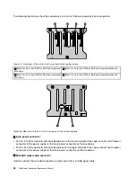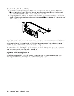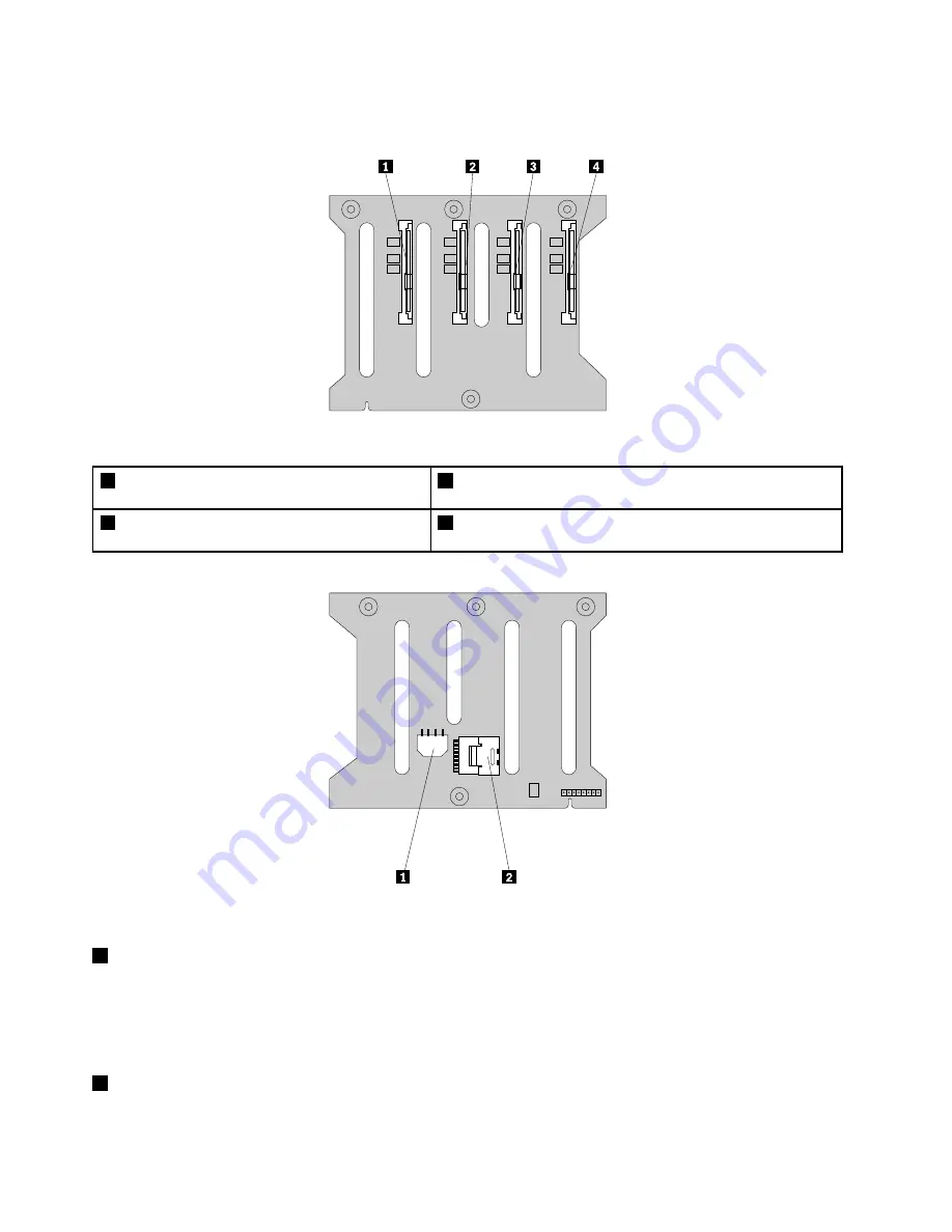
The following illustrations show the connectors on a 3.5-inch hot-swap hard disk drive backplane.
Figure 19. Front view of the 3.5-inch hot-swap hard disk drive backplane
1
Slot 0 for a 3.5-inch SATA or SAS hot-swap hard
disk drive
3
Slot 2 for a 3.5-inch SATA or SAS hot-swap hard disk drive
2
Slot 1 for a 3.5-inch SATA or SAS hot-swap hard
disk drive
4
Slot 3 for a 3.5-inch SATA or SAS hot-swap hard disk drive
Figure 20. Rear view of the 3.5-inch hot-swap hard disk drive backplane
1
8-pin power connector
• For 3.5-inch hot-swap hard disk drive backplane on the lower hard disk drive cage, connect the P5 power
connector of the power supply to the 8-pin power connector on the backplane.
• For 3.5-inch hot-swap hard disk drive backplane on the upper hard disk drive cage, connect the P4 power
connector of the power supply to the 8-pin power connector on the backplane.
2
Mini-SAS signal cable connector
Used to connect the mini-SAS connector on one end of the mini-SAS signal cable.
36
ThinkServer Hardware Maintenance Manual
Содержание THINKSERVER 387
Страница 1: ...ThinkServer Hardware Maintenance Manual Machine Types 0387 0388 0389 0390 0391 0392 0393 and 0441 ...
Страница 16: ...4 ThinkServer Hardware Maintenance Manual ...
Страница 18: ...6 ThinkServer Hardware Maintenance Manual ...
Страница 94: ...82 ThinkServer Hardware Maintenance Manual ...
Страница 190: ...178 ThinkServer Hardware Maintenance Manual ...
Страница 228: ...216 ThinkServer Hardware Maintenance Manual ...
Страница 246: ...234 ThinkServer Hardware Maintenance Manual ...
Страница 247: ......
Страница 248: ......

