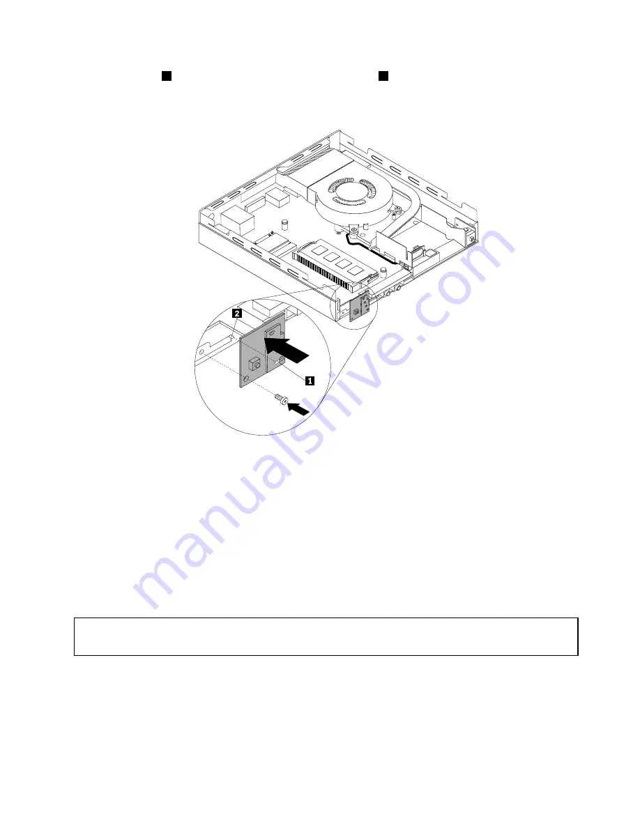
7. Align the hole
1
in the new power switch board with the tab
2
on the computer and position the new
power switch board onto the chassis. Then, install the screw to secure the new power switch board
on the chassis.
Figure 48. Installing the power switch board
8. Connect the power switch board cable to the power switch board cable connector on the system board.
See “Locating parts on the system board” on page 12.
9. Reinstall the hard disk drive assembly. See “Installing or removing the hard disk drive assembly”
on page 57.
What to do next:
• To work with another piece of hardware, go to the appropriate section.
• To complete the installation or replacement, go to “Completing the parts replacement” on page 80.
Replacing the Wi-Fi card module
Attention:
Do not open your computer or attempt any repair before reading and understanding the “Important safety information”
on page v.
This section provides instructions on how to replace the Wi-Fi card module.
Note:
The Wi-Fi card module is only available in some models.
To replace the Wi-Fi card module, do the following:
1. Turn off the computer and disconnect all power cords from electrical outlets.
2. Remove the computer cover. See “Removing the computer cover” on page 55.
Chapter 5
.
Installing or replacing hardware
63
Содержание M93/p Tiny
Страница 1: ...ThinkCentre M93 p Tiny User Guide Machine Types 10A4 10A5 10AA and 10AB ...
Страница 6: ...iv ThinkCentre M93 p Tiny User Guide ...
Страница 36: ...24 ThinkCentre M93 p Tiny User Guide ...
Страница 136: ...124 ThinkCentre M93 p Tiny User Guide ...
Страница 142: ...130 ThinkCentre M93 p Tiny User Guide ...
Страница 146: ...134 ThinkCentre M93 p Tiny User Guide ...
Страница 149: ...Appendix E China Energy Label Copyright Lenovo 2013 2014 137 ...
Страница 150: ...138 ThinkCentre M93 p Tiny User Guide ...
Страница 152: ...140 ThinkCentre M93 p Tiny User Guide ...
Страница 156: ...144 ThinkCentre M93 p Tiny User Guide ...
Страница 157: ......
Страница 158: ......


