Procedure
Step 1. Touch the static-protective package that contains the drive to any unpainted surface on the outside
of the server. Then, take the drive out of the package and place it on a static-protective surface.
Note:
Ensure that drive installation meets “Drive bay configurations and requirements” on page
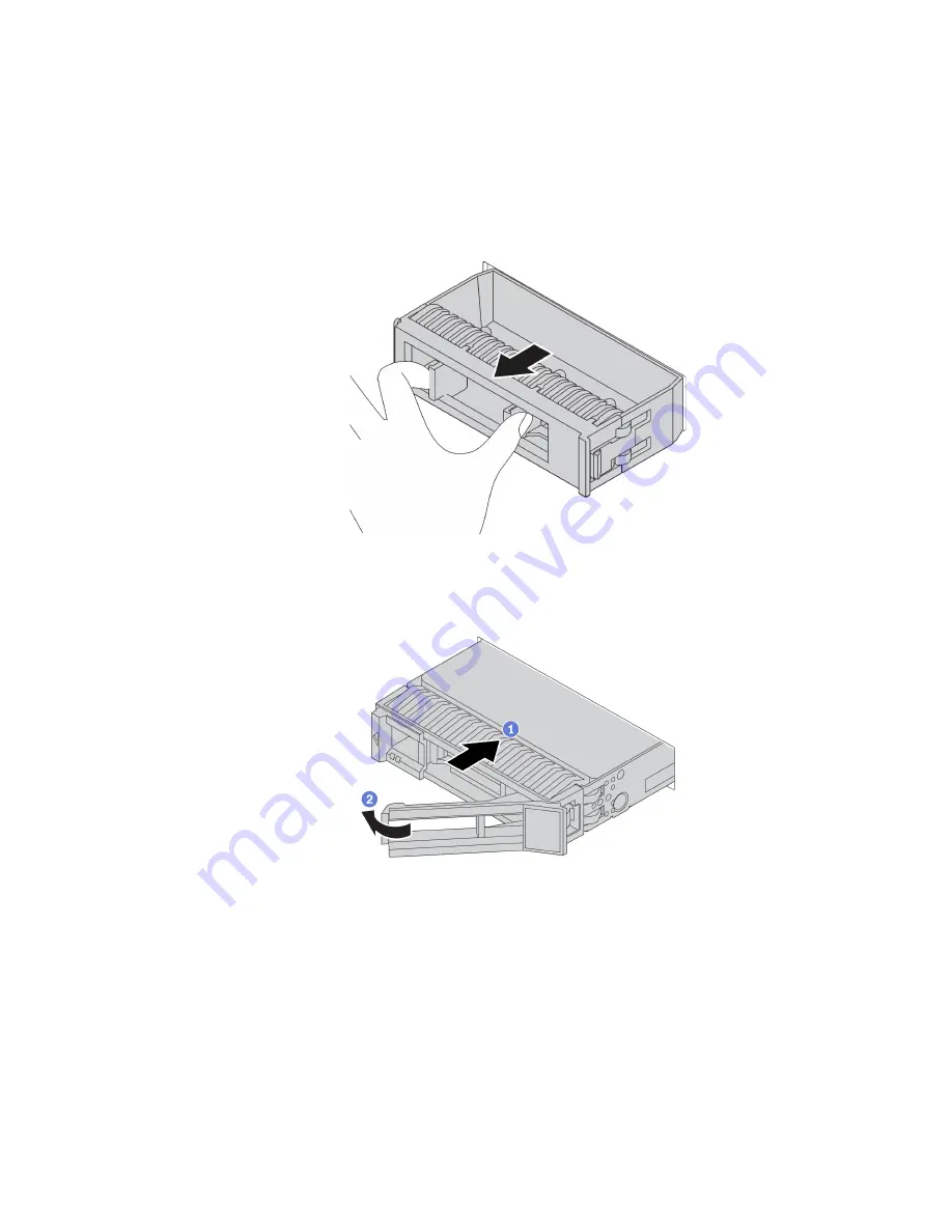
Step 2. Remove the drive filler from the drive bay and keep the drive filler in a safe place.
Figure 64. Drive filler removal
Step 3. Install the drive in the drive bay.
Figure 65. Hot-swap drive installation
a. Ensure that the drive tray handle is in the open position. Slide the drive into the drive bay until it
snaps into position.
b. Close the drive tray handle to lock the drive in place.
Step 4. Check the drive status LED to verify that the drive is operating correctly.
a. If the yellow drive status LED is lit continuously, that drive is faulty and must be replaced.
b. If the green drive activity LED is flashing, the drive is being accessed.
Step 5. Continue to install additional hot-swap drives if necessary.
After you finish
.
Hardware replacement procedures
179
Содержание 7D2V
Страница 1: ...ThinkSystem SR665 Maintenance Manual Machine Types 7D2V and 7D2W ...
Страница 6: ...iv ThinkSystem SR665 Maintenance Manual ...
Страница 10: ...viii ThinkSystem SR665 Maintenance Manual ...
Страница 66: ...56 ThinkSystem SR665 Maintenance Manual ...
Страница 82: ...Figure 25 Cable routing for configuration 4 72 ThinkSystem SR665 Maintenance Manual ...
Страница 111: ...BP 3 NVMe 2 3 PCIe 3 BP 3 NVMe 4 5 PCIe 7 BP3 NVMe 6 7 PCIe 8 Chapter 3 Internal cable routing 101 ...
Страница 123: ...Figure 40 Cable routing for configuration 1 Chapter 3 Internal cable routing 113 ...
Страница 126: ...Figure 42 Cable routing for configuration 2 116 ThinkSystem SR665 Maintenance Manual ...
Страница 131: ...Figure 45 Cable routing for configuration 6 Chapter 3 Internal cable routing 121 ...
Страница 133: ...Chapter 3 Internal cable routing 123 ...
Страница 148: ...138 ThinkSystem SR665 Maintenance Manual ...
Страница 167: ...Chapter 4 Hardware replacement procedures 157 ...
Страница 216: ...Step 2 Connect the cables to the backplanes See 7mm drives on page 64 206 ThinkSystem SR665 Maintenance Manual ...
Страница 237: ...Chapter 4 Hardware replacement procedures 227 ...
Страница 299: ...Chapter 4 Hardware replacement procedures 289 ...
Страница 300: ...On the 2 5 inch middle drive cage 290 ThinkSystem SR665 Maintenance Manual ...
Страница 339: ...Chapter 4 Hardware replacement procedures 329 ...
Страница 364: ...354 ThinkSystem SR665 Maintenance Manual ...
Страница 408: ...398 ThinkSystem SR665 Maintenance Manual ...
Страница 431: ...5 Reseat the failing device 6 Replace the failing device Chapter 5 Problem determination 421 ...
Страница 444: ...434 ThinkSystem SR665 Maintenance Manual ...
Страница 445: ... Copyright Lenovo 2019 435 ...
Страница 448: ...438 ThinkSystem SR665 Maintenance Manual ...
Страница 449: ... Copyright Lenovo 2019 439 ...
Страница 452: ...442 ThinkSystem SR665 Maintenance Manual ...
Страница 464: ...454 ThinkSystem SR665 Maintenance Manual ...
Страница 465: ......
Страница 466: ......


