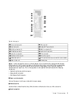

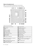
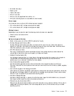

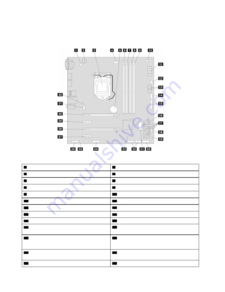
Parts on the system board
Note:
The system board might look slightly different from the illustrations.
The following illustration shows the locations of the parts on the system board.
Figure 4. Parts on the system board
1
PS/2 keyboard and mouse connector
2
4-pin power connector
3
Microprocessor
4
Microprocessor fan connector
5
Battery
6
Memory slot 1 (DIMM1)
7
Memory slot 2 (DIMM2)
8
Memory slot 3 (DIMM3)
9
Memory slot 4 (DIMM4)
10
Thermal sensor connector
11
10-pin power connector
12
Hard-disk-drive fan connector
13
4-pin SATA power connectors
14
Thunderbolt
™
connector
15
Parallel connector
16
eSATA connector
17
SATA connectors
18
Power fan connector
19
USB hardware disable header
20
Front bezel connector (for connecting LED indicators
and the power button)
21
Front USB 3.0 connector (for connecting USB
connectors on the front panel)
22
USB 2.0 connectors (for connecting front USB 2.0
connector, card reader connector, or Bluetooth
connector)
23
Clear CMOS (Complementary Metal Oxide
Semiconductor) /Recovery jumper
24
Serial (COM2) connector
25
Internal speaker connector
26
Front audio connector
6
P320 User Guide
Содержание 30BG
Страница 1: ...P320 User Guide Machine Types 30BJ 30BK and 30BS ...
Страница 12: ...x P320 User Guide ...
Страница 28: ...16 P320 User Guide ...
Страница 40: ...28 P320 User Guide ...
Страница 46: ...34 P320 User Guide ...
Страница 56: ...44 P320 User Guide ...
Страница 120: ...108 P320 User Guide ...
Страница 124: ...112 P320 User Guide ...
Страница 126: ...114 P320 User Guide ...
Страница 128: ...116 P320 User Guide ...
Страница 136: ...124 P320 User Guide ...
Страница 138: ...Ukraine RoHS India RoHS RoHS compliant as per E Waste Management Rules Taiwan RoHS 126 P320 User Guide ...
Страница 140: ...4 Follow the instructions on the screen 128 P320 User Guide ...
Страница 142: ...130 P320 User Guide ...
Страница 144: ...132 P320 User Guide ...
Страница 145: ......
Страница 146: ......