Page 10
506083−01 03/08
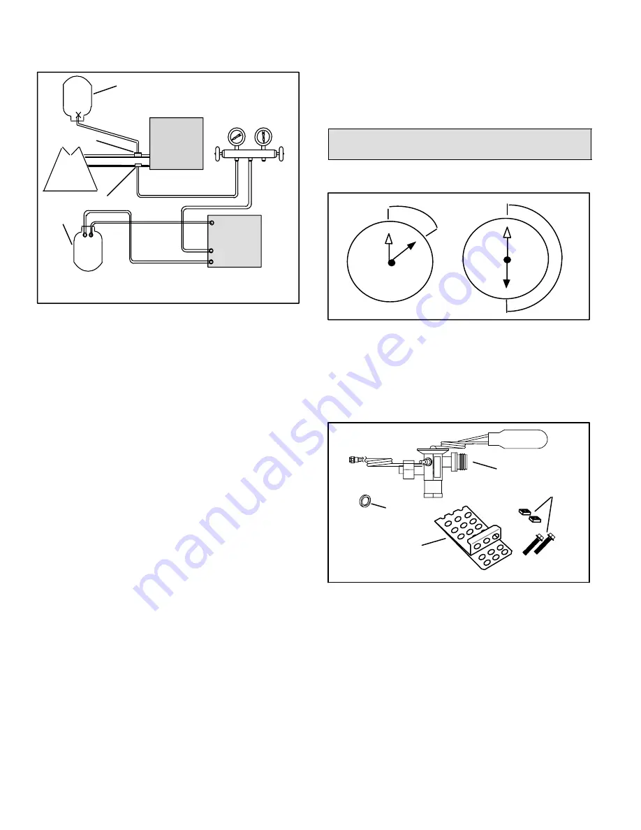
Two gauge sets (one for HCFC−22; one for
HFC−410A).
LOW
PRESSURE
HIGH
PRESSURE
EXISTING
INDOOR
UNIT
GAUGE
MANIFOLD
INVERTED HCFC−22 CYLINDER
CONTAINS CLEAN HCFC−22 TO
BE USED FOR FLUSHING.
LIQUID LINE SERVICE VALVE
INLET
DISCHARGE
TANK
RETURN
CLOSED
OPENED
RECOVERY
CYLINDER
NOTE − The inverted HCFC−22 cylinder must contain at least the same
amount of refrigerant as was recovered from the existing system.
RECOVERY MACHINE
NEW
OUTDOOR
UNIT
SUCTION LINE
SERVICE VALVE
SUCTION
LIQUID
Figure 18. Typical Flushing Connection
FLUSHING PROCEDURE
1. Connect the following:
HCFC−22 cylinder with clean refrigerant to the
suction service valve,
HCFC−22 gauge set to the liquid line valve,
Recovery machine with an empty recovery tank to
the gauge set.
2. Set the recovery machine for liquid recovery and start
the recovery machine. Open the gauge set valves to
allow the recovery machine to pull a vacuum on the
existing system line set and indoor unit coil.
3. Invert the cylinder of clean HCFC−22 and open its
valve to allow liquid refrigerant to flow into the system
through the suction line valve. Allow the refrigerant to
pass from the cylinder and through the line set and the
indoor unit coil before it enters the recovery machine.
4. After all of the liquid refrigerant has been recovered,
switch the recovery machine to suction recovery so
that all of the HCFC−22 is recovered. Allow the
recovery machine to pull a vacuum on the system.
5. Close the valve on the inverted HCFC−22 drum and
the gauge set valves. Pump the remaining refrigerant
out of the recovery machine and turn the machine off.
6. Use dry nitrogen to break the vacuum on the
refrigerant lines and indoor unit coil before removing
the recovery machine, gauges and HCFC−22
refrigerant drum.
Installing New Indoor Unit Metering
Device
TSA*H4 units are used in thermal expansion valve (TXV)
systems only.
1
2
3
4
5
6
7
8
9
10
11
12
1/8 TURN
1
2
3
4
5
6
7
8
9
10
11
12
1/2 TURN
Figure 19. Tightening Distance
TSA*H4
ENGINEERING HANDBOOK
See the TSA*H4
Engineering Handbook
for approved
indoor/outdoor match−ups, applicable TXV kit, and
application information.
Figure 20 illustrates the typical TXV kit parts and
quantities.
TXV (1)
COPPER
MOUNTING
STRAP (1)
HEX HEAD BOLTS
AND NUTS (2)
TEFLON
RINGS (2)
Figure 20. TXV Kit Components


