background image

17

Unit Start-Up

IMPORTANT

Units should be energized 24 hours before unit start-up 

to prevent compressor damage as a result of slugging.

1. 

Inspect all factory- and field-installed wiring for loose 

connections.

2.  Verify that the manifold gauge set is connected.
3.  Add additional refrigerant charge if required before 

opening valves and while system is still under a 

vacuum.

4. 

Open the liquid and gas line service valves to release 

the refrigerant charge contained in outdoor unit into 

the system.

5.  Replace the stem caps and tighten to the value listed 

in “Table 4. Flare Nut Torque Recommendations” on 

page 12.

6.  Check voltage supply at the outdoor unit terminal strip. 

The voltage must be within the range listed on the 

unit’s nameplate. If not, do not start the equipment 

until you have consulted with the power company and 

the voltage condition has been corrected.

7.  Refer to the included user guide to operate the system 

using the provided remote control.

8.  Visually check for binding of both indoor and outdoor 

fans.

Adding Refrigerant for Longer Line Set

The outdoor unit is factory-charged with refrigerant. 

Calculate the additional refrigerant required according to 

the diameter and the length of the liquid pipe between the 

outdoor unit and indoor unit connections.

Be sure to add the proper amount of additional refrigerant. 

Failure to do so may result in reduced performance.
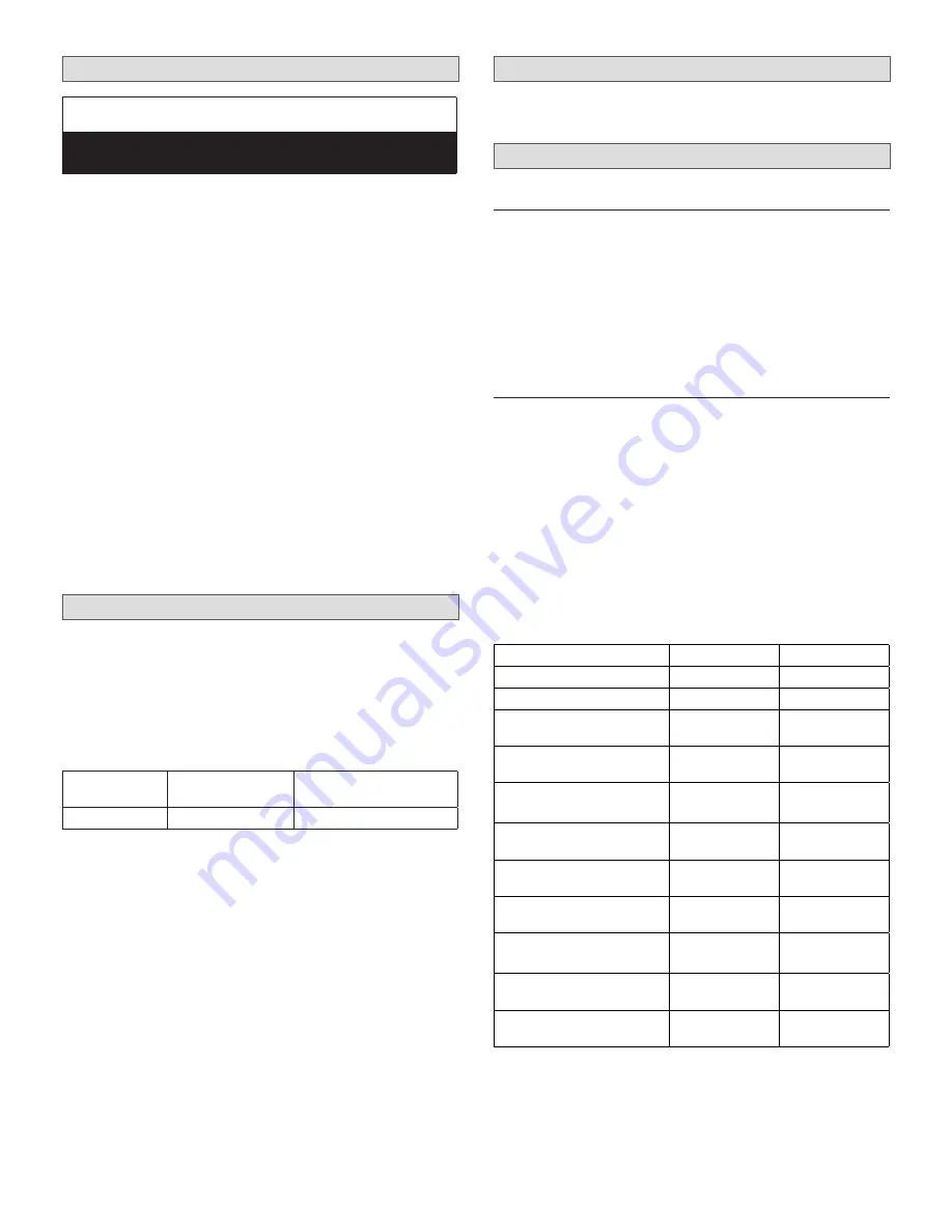
Table 8. 

Additional Refrigerant Charge

System Size 

(KBtu)

Pipe Length


(feet / meters)

Amount of Refrigerant 

to add

12

>25 (7.5)

0.161 oz/ft (15g/m)

Troubleshooting

See  “Error  Codes”  on  page  19  for  details  on 

troubleshooting.

Test Run

Pre-Checks

Only  perform  test  run  after  you  have  completed  the 

following steps:

• 

Electrical Safety Checks – Confirm that the unit’s elec

-

trical system is safe and operating properly

• 

Refrigerant Leak Checks – Check all flare nut connec

-

tions and confirm that the system is not leaking

• 

Confirm that liquid and gas valves are fully open

Procedure

You should perform the Test Run for at least 30 minutes.

1.  Connect power to the unit.
2. 

Press the ON/OFF button on the remote controller to 

turn it on.

3.  Press the mode button to scroll through the following 

functions, one at a time:

• 

COOL - Select lowest possible temperature

• 

HEAT - Select highest possible temperature

4.  Let each function run for 5 minutes, and perform the 

following checks:

Table 9. 

Test Run Checklist

Checks

Pass

Fail

No electrical leakage
Unit is properly grounded
All electrical terminals 

properly covered
Indoor and outdoor units are 

solidly installed
All pipe connection points do 

not leak

Outdoor

(2):

Indoor

(2):

Water drains properly from 

drain hose
All piping is properly 

insulated

Unit performs COOL function 

properly

Unit performs HEAT function 

properly

Indoor unit louvers rotate 

properly
Indoor unit responds to 

remote controller

Содержание M0STAT60Q-1

Страница 1: ...lean up All mini split operating conditions must be verified ac cording to these installation instructions MLA MPB and MFMA Series SINGLE ZONE MINI SPLIT SYSTEMS 208 230V Floor Mount Console 508048 01...

Страница 2: ...ccessories Component Catalog Number M0STAT64Q 1 Programmable Wired Controller 15D30 Wired Controller Extension Cable 20 feet long Y8738 Indoor Outdoor Unit Match Ups Outdoor Unit Indoor Unit Voltage M...

Страница 3: ...ence 1 1st Revision Voltage P 208 230V 1 phase 60hz Nominal Cooling Capacity 012 1 ton Unit Type L Low Ambient Heat Pump P Heat Pump CEILING FLOOR NON DUCTED INDOOR UNITS M FM A 012 S 4 2 P Unit Type...

Страница 4: ...rated tape field provided Wiring Condensate drain line wrapped in foam insulation Refrigerant Line Set Condensate Line And Indoor Outdoor Cable field provided Tape Line set wrapped in foam insulation...

Страница 5: ...2S4S P inches 34 1 4 20 1 4 21 7 8 13 1 8 13 3 8 mm 870 514 556 333 340 MLA012S4S P inches 34 1 4 20 1 4 21 3 4 12 1 4 13 3 8 mm 870 514 552 311 594 Indoor Units Hanging Brackets 2 FRONT VIEW SIDE VIE...

Страница 6: ...e 6 inches 152 mm when mounted on brackets and with no obstructions on the other three sides Figure 3 Outdoor Unit Clearances Inches mm Indoor Unit FRONT VIEW SIDE VIEW 4 102 WALL SUPPLY AIR 40 1016 S...

Страница 7: ...sed to strong electromagnetic forces Areas exposed to acids or alkaline detergents DO Place the unit so that it is not exposed to direct sun light Ensure the structural ceiling can support the weight...

Страница 8: ...er several times per year to avoid corrosive buildup salt Some localities are adopting sound ordinances based on the unit s sound level registered from the adjacent property not from the property wher...

Страница 9: ...et 12 in 305 mm 79 in 2007 mm Figure 9 Outdoor Unit Air Flow Obstructed by Snow Figure 10 Avoid Defrost Water Ice Hazard Prevailing Winds Normally wind baffles are not required for a outdoor unit Howe...

Страница 10: ...l mounting brack et insert the provided drain connector into one of the 1 inch 25 mm drain holes and attached a field provided insulated drain hose to the connector Use field provid ed rubber plugs to...

Страница 11: ...ength required for the application 4 Cut the selected pipes with a pipe cutter Make the cuts flat and smooth as illustrated in Figure 18 Cutting Pipe 9 0 Lean Crude Burr o Figure 18 Cutting Pipe 5 Ins...

Страница 12: ...ON THE OUTSIDE OF THE FLARE MALE FLARE CONNECTION Figure 19 Making Connections Male to Female Connection 17 Once snug continue another half turn on each nut which should create a leak free joint A to...

Страница 13: ...non condensables and moisture from the system Leak Test Use the following procedure to test for system leaks 1 Connect the manifold gauge set and dry nitrogen gas cylinder to the liquid and gas servic...

Страница 14: ...ons are complete Indoor Unit All indoor units are powered by the outdoor unit Communication Wiring Indoor Units 30K and Below Use one stranded 4 conductor wire to provide power and communication Commu...

Страница 15: ...g Factory Setting For Setting Down louver For Setting Down louver SW101 SW101 ACTIVE ACTIVE 1 1 2 2 ON ON 1 1 2 2 ON ON 1 1 2 2 ON ON 1 1 2 2 ON ON SW103 SW103 For Setting Fan Motor Control then No Po...

Страница 16: ...G CN 21 Y G CN 1A Y G Y G COMPRESSOR Y G CN 50 3 U V W BLUE RED BLACK EXV OUTDOOR MAIN PCB OUTDOOR TE MP S E NS OR COMPR E S S OR DIS CHAR GE TE MP S E NS OR OUTDOOR C OIL TEMP SENSOR RED BLACK WHTIE...

Страница 17: ...amount of additional refrigerant Failure to do so may result in reduced performance Table 8 Additional Refrigerant Charge System Size KBtu Pipe Length feet meters Amount of Refrigerant to add 12 25 7...

Страница 18: ...failure the system will immediately stop When power returns the Operation light on the indoor unit will flash To restart the unit press the ON OFF button on the remote control If the system has an aut...

Страница 19: ...Figure 30 Open Front Panel 2 Remove the Air Filter Press the clamps on the right and left sides of the air filter down slightly then pull upward to remove the air filter Air Outlet Selection Switch Fi...

Страница 20: ...actory installed CN4 Adapter Cable Optional Programmable Wired Controller 20 Foot Cable provided with Programmable Wired Controller Figure 33 Connecting Optional Programmable Wired Controller Connect...

Отзывы: