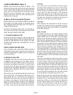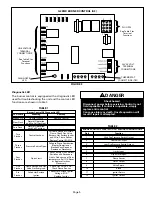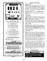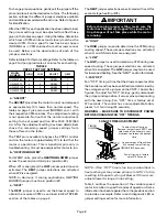
Page 9
TABLE 5
VSP2–1 OPERATION
HEATING MODE
COOLING MODE
UNITS WITH
SINGLE–STAGE HEATING
UNITS WITH
TWO–STAGE HEATING
UNITS WITH SINGLE–
SPEED COMPRESSOR
UNITS WITH TWO–SPEED
COMPRESSOR
NON–ZONED
APPLICATIONS
When a single-stage thermostat is
used and full heating input of the
unit is required, jump terminals W1
and W2 on the burner control
board.
The
HEAT
LED-DS2 is lit when the
thermostat calls for heat. The
ON/
OFF
LED-DS3 is lit after 110 seconds
(65 seconds pre-purge and 45 se-
conds fan “ON” time) from the time
a call for heat is made. This indicates
the blower is operating in heating
speed.
NON–ZONED
APPLICATIONS
Using a two-stage thermostat with
first-stage (W1) calling, the
ON/OFF
LED-DS3 is lit to indicate the blower
is operating in low speed.
When the
ON/OFF
LED-DS3 and
HEAT
LED-DS2 are lit, the blower is
operating in heating speed and se-
cond-stage (W2) heating is calling.
HEAT
LED-DS2 is lit with a call for
heat from the thermostat.
ON/OFF
LED-DS3 is lit after 110 seconds
from the time a call for heat is made.
NOTE—In two-stage operation and
when there is a call for first-stage
only, the unit will always start on
high heat (second-stage) and will
automatically switch to first-stage
operation after initial unit warm-up.
NON–ZONED
APPLICATIONS
The terminals “DS” and “Y” must be
jumpered together. With a call for
cooling, terminals G, Y and DS on
the unit control board are energized
from the thermostat.
HI/LOW
LED–
DS1 and
ON/OFF
LED–DS3 are lit to
indicate the blower is operating on
high speed.
NOTE—“Y” and “DS” must be
jumpered for single-stage cooling,
non-zoned applications.
NON–ZONED
APPLICATIONS
The
ON/OFF
LED–DS3 is lit to indicate
the blower is operating in first stage
cooling. This LED is energized on
when a 24VAC thermostat demand is
supplied to the control (terminal “G”
on the control box terminal strip).
In second stage, the
ON/OFF
LED–
DS3 and
HI/LOW
LED–DS1 are lit to
indicate the blower is operating on
high speed (24VAC is supplied to the
unit terminal strip “Y2” from “Y2”
on the thermostat).
NOTE—“Y2” must be jumpered to
“DS” in two–speed, non–zoned
applications.
HARMONY ZONED
APPLICATIONS
The blower speed is controlled by
the PWM (pulse width modulation)
signal sent from the control center
of the zoning system to the terminal
strip’s “DS” terminal.
HI/LOW
LED–
DS1 and
ON/OFF
LED–DS3 are lit to
indicate the blower is operating.
NOTE–In Harmony II zoning ap-
plications, HTG. BLOWER jumper
must be in position #2.
HARMONY ZONED
APPLICATIONS
The blower speed is controlled by
the PWM (pulse width modulation)
signal sent from the control center
of the zoning system to the terminal
strip’s “DS” terminal.
HI/LOW
LED–
DS1 and
ON/OFF
LED–DS3 are lit to
indicate the blower is operating.
HARMONY ZONED
APPLICATIONS
The blower speed is controlled by
the PWM (pulse width modulation)
signal sent from the control center
of the zoning system to the terminal
strip’s “DS” terminal.
HI/LOW
LED–
DS1 and
ON/OFF
LED–DS3 are lit to
indicate the blower is operating.
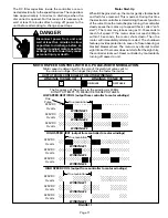
NOTE: For zone applications with Harmony, remove wire from VSP #3 terminal on burner control board, insulate end and secure
to prevent from shorting.
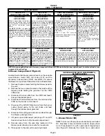
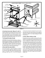
B–Blower Compartment (Figure 8)
Located inside the blower compartment are the variable
speed blower motor (B3), coil choke (L13), and the
secondary limit switches [(1)S21 and (2)S21]. To access
the blower compartment follow the steps outlined below:
1– Remove the two screws holding the blower panel to
the unit.
2– Remove the two screws (located in the middle of the
blower panel) holding the grommet for the VSP2
JP46 wires.
3– Disconnect the jack (J46) from the VSP2 and feed it
through the blower panel.
4– Disconnect thermostat wires from the terminal strip
(TB1) on the burner control board.
5– Disconnect the 120VAC (black) wire from the burner
control board going to the coil choke and feed
through the blower panel grommet.
6– Disconnect line voltage wire (white) and feed through
the blower panel grommet.
7– Lift panel up and disconnect jack plugs JP1 and JP2
(brown wires) found in the blower compartment.
8– Remove wires from the wire clips located on the
blower panel allowing more wire for movement.
9– Place panel to the side, while servicing blower.
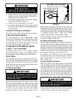
FIGURE 7
G25MV BLOWER DOOR COMPONENTS –
BLOWER ACCESS
W
W
BRN
BRN
BLK
G25MV
SHOWN
IN UPFLOW
POSITION
5
6
7
8
1
2
3
4
1
1– Blower Motor (B3)
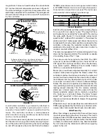
G25MV units use a three-phase, electronically controlled
D.C. brushless motor (controller converts single phase
a.c. to three phase D.C.), with a permanent-magnet-type
rotor (figure 9). Because this motor has a permanent


