Page 18
Manifold Pressure Check Procedure:
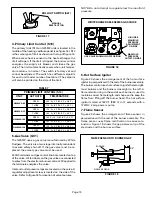
1– Connect a test gauge to outlet pressure tap on gas
valve. Start unit and allow 5 minutes for unit to
reach steady state.
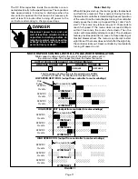
2– While waiting for the unit to stabilize, notice the
flame. Flame should be stable and should not lift
from burner. Natural gas should burn blue.
3– After allowing unit to stabilize for 5 minutes, record
manifold pressure and compare to the normal
manifold pressure of 3.5” W.C. (870.2 Pa) for high
fire operation or 1.7” W.C. (422.7 Pa) for low fire.
NOTE–Shut unit off, turn gas valve to “OFF” position
and remove manometer as soon as an accurate
reading has been obtained. Take care to replace
pressure tap plug.
F– Proper Gas Flow
To check for proper gas flow to combustion chamber,
determine Btuh input from unit rating plate or the
specifications tables on page 2. Divide input rating by
Btuh per cubic foot of available gas. Result is the number
of cubic feet per hour required. Determine flow of gas
through gas meter for two minutes. Multiply by 30 to get
hourly flow of gas to burner.
NOTE– To obtain accurate reading, shut off all other
gas appliances connected to meter.
G–High Altitude Derate
A.G.A. certified units must be derated 4 percent for each
1,000 feet (305m) above sea level. Thus, at an altitude of
4000 feet (1210 m), the unit would require a derate of 16
percent.
C.G.A. certified units must be derated 10 percent for
elevations 2000 feet (610 m) to 4500 feet (1370 m)
above sea level.
NOTE–In Canada, use the following high altitude
conversion kits: LB–79766A for G25MV3–60/75; and
LB–79766B for G25MV5–100/120.
NOTE–This is the only permissible field derate for
this appliance.
IMPORTANT
For safety, shut unit off and remove manometer as
soon as an accurate reading has been obtained.
Take care to replace pressure tap plug.
H–Flame Signal
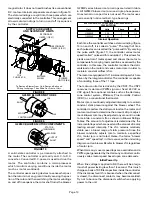
A 20 microamp DC meter is needed to check the flame
signal on the primary ignition control. Use a flame signal
transducer (part number 78H5401) available from Lennox
to measure the flame signal.
Flame (microamp) signal is an electrical current which
passes from the ignition control through the sensor
electrode during unit operation. Current passes from
the sensor through the flame to ground to complete a
safety circuit.
To Measure Flame Signal:
1– Remove front louvered panel and disconnect the
sensor wire from the flame sensor.
2– Place meter in series between flame sensor and
sensor wire. Connect the positive (+) lead of meter
to the sensor wire and the negative (–) lead of the
meter to the flame sensor.
3– Set thermostat for a heating demand and check
flame signal with unit operating. For G25MV series,
a reading of 4 to 6 microamps DC should occur. The
ignition control must see at least 1.5 microamps in
order to keep the gas valve energized.
Flame signal may rise above 5 microamps for the first few
seconds after ignition then level off within the range.
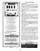
I–Electronically Controlled Blower Motor
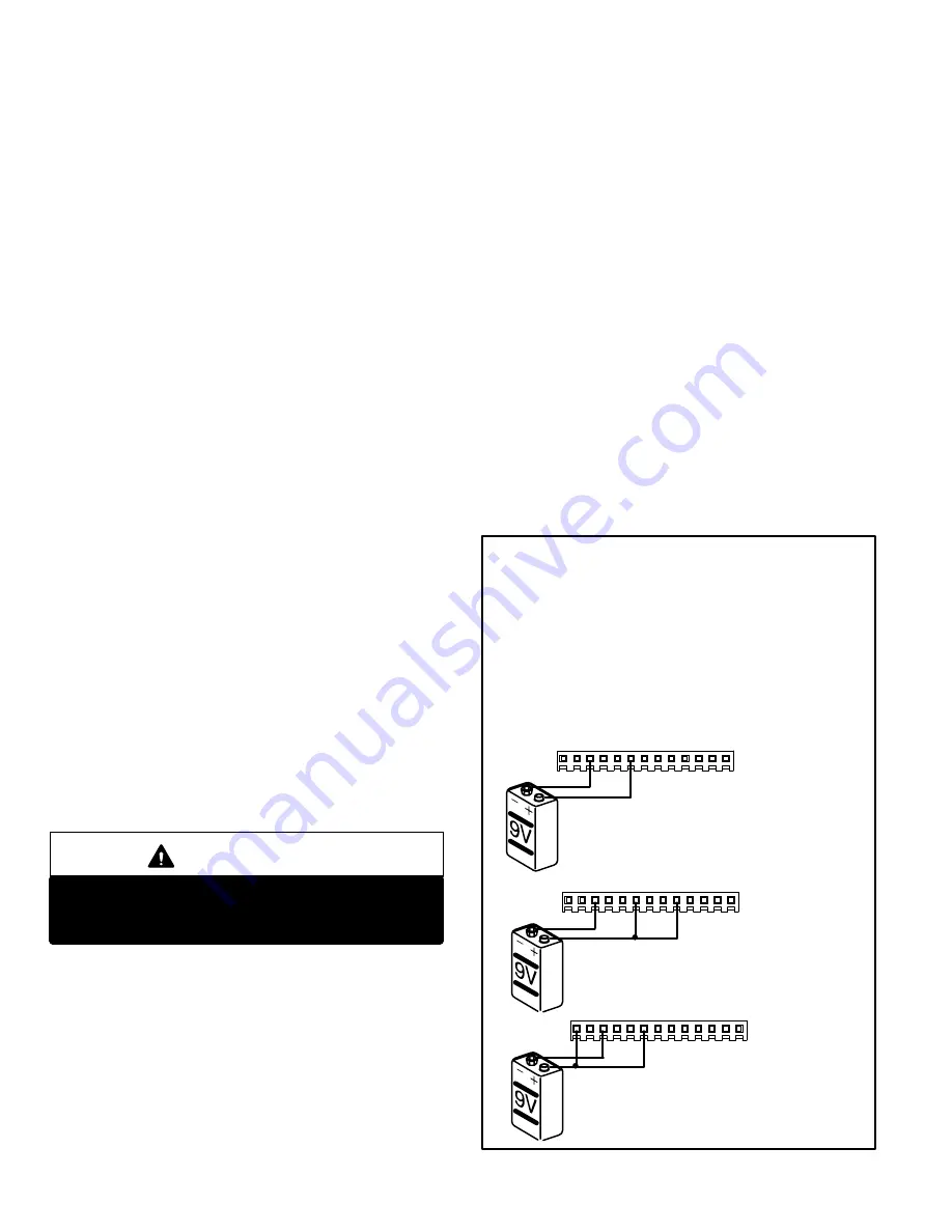
To check–out the VSM blower and the VSP2–1 blower
control board, begin with the VSM blower. Refer to figure
23 and follow the check–out procedure as outlined. If the
blower fails any of these tests, do not attempt to repair
the VSM blower. There are no field serviceable parts in
this component. Replace the motor and repeat the check–
out procedure. To verify proper operation of the VSP2–1,
check the board as outlined in the troubleshooting flow-
charts on the last page.
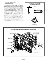
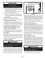
VSM CHECK–OUT
1– Disconnect power to unit.
2– Disconnect 13 pin plug J46 from P46 located on
VSP2–1.
3– Connect voltage source as shown above.
4– Turn on power to unit. Blower should
operate at low speed.
VSM LOW SPEED CHECK–OUT
NOTE–Any A.C. voltage source less than 30 volts or any D.C. voltage
source less than 20 volts may be used to check out the motor. An ordi-
nary 9 volt battery is recommended. Unit transformer T1 secondary
may be used in lieu of a battery. A 9 volt battery will last for about one
day of normal operation. If transformer T1 is used, double check all
wiring connections before placing unit back in operation.
CHECK–OUT PROCEDURE USING J46
5– Disconnect power to unit.
6– Connect voltage source as shown above.
7– Turn on power to unit. Blower should operate at
high speed.
VSM HIGH SPEED
CHECK–OUT
8– Disconnect power to unit.
9– Connect voltage source as shown above.
10–Turn on power to unit. Blower should operate at
heating speed.
VSM HEATING SPEED CHECK–OUT
FIGURE 23
A kit is available from the Lennox parts center to use in testing
the variable speed motor. The kit 70J11 includes a test plug har-
ness to facilitate vsm check–out.
Follow testing procedures
outlined in the instructions provided with the kit. The testing
procedures are different than those listed below.
If not using the kit to test the motor, follow the procedure below.
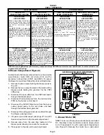
J46
J46
J46

