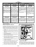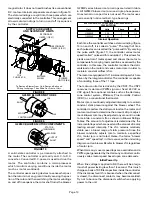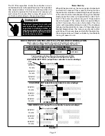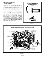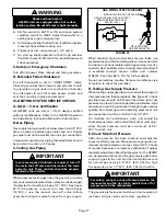
FIGURE 24
STATIC PRESSURE
TEST
MANOMETER
G25MV UNIT
Page 19
V–TYPICAL OPERATING CHARACTERISTICS
A–Blower Operation and Adjustment
NOTE– The following is a generalized procedure
and does not apply to all thermostat controls.
1– Blower operation is dependent on thermostat
control system.
2– Generally, blower operation is set at thermostat
subbase fan switch. With fan switch in ON position,
blower operates continuously on heating speed.
With fan switch in AUTO position, blower cycles
with demand or runs continuously while heating or
cooling circuit cycles.
3– In all cases, blower and entire unit will be off when
the system switch is in OFF position.
B–Temperature Rise
Temperature rise for G25MV units depends on unit input,
blower speed, blower horsepower and static pressure as
marked on the unit rating plate. The blower speed must
be set for unit operation within the range of “AIR TEMP.
RISE
°
F” listed on the unit rating plate.
To Measure Temperature Rise:
1– Place plenum thermometers in the supply and return
air plenums. Locate supply air thermometer in the
first horizontal run of the plenum where it will not pick
up radiant heat from the heat exchanger.
2– Set thermostat to highest setting.
3– After plenum thermometers have reached their
highest and steadiest readings, subtract the two
readings. The difference should be in the range
listed on the unit rating plate. If the temperature is
too low, decrease blower speed. If temperature is
too high, first check the firing rate. Provided the firing
rate is acceptable, increase blower speed to reduce
temperature. To change blower speed taps see the
Blower Speed Taps section in this manual.
C–External Static Pressure
1– Measure tap locations as shown in figure 24.
2– Punch a 1/4” diameter hole
in supply and return air
plenums. Insert manome-
ter hose flush with inside
edge of hole or insulation.
Seal around the hose with
permagum. Connect the
zero end of the manometer
to the discharge (supply) side of the system. On
ducted systems, connect the other end of manometer
to the return duct as above. For systems with
non–ducted returns, leave the other end of the
manometer open to the atmosphere.
3– With only the blower motor running and the
evaporator coil dry, observe the manometer
reading. Adjust blower motor speed to deliver
the air desired according to the job requirements.
4– External static pressure drop must not be more
than 0.8” W.C. (198.9 Pa).
5– Seal around the hole when the check is complete.
VI–MAINTENANCE
At the beginning of each heating season, the system
should be checked as follows:
A–Filters
Return air filter is supplied with unit. A filter must be
used in order to ensure long life and proper operation.
The filter is located in the return air duct or return air
register. Filters must be cleaned or replaced when
dirty to assure proper unit operation.
B–Cleaning Heat Exchanger and Burners
NOTE–Use papers or protective covering in front of
furnace while cleaning furnace.
To clean heat exchanger and burners:
1– Turn off both electrical and gas power supplies to
furnace. Refer to figure 1 during disassembly and
reassembly procedures.
2– Disconnect wires leading to burner and heat ex-
changer assembly.
3– Remove front louvered panel and and blower access
panels.
4– Remove flue pipe and draft hood.
5– Disconnect gas piping and move piping out of way
so heat exchanger can slide out front of cabinet.
6– Gas manifold, gas valve, burners and combustion
air blower do not need to be removed and can be
left in place.
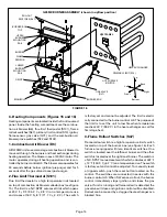
7– Locate four screws which hold heat exchanger in
place (two on each side of cabinet). See figure 25.
Remove screws.
8– Slide heat exchanger out of cabinet.
To clean burners:
9– Remove screws holding upper burner mounting rail
(figure 16). Remove rail.
10– Slide burners off each orifice and pull burners from
heat exchanger.
11– Clean holes in burner head (retention ring) with a
wire brush. See figure 20.
12– With a shop vacuum or rags, clean out soot and
scale deposits from burners.
13– Remove screws securing flue box to vestibule
panel. Remove flue box from unit. Leave combustion
air blower attached to flue box.
14– With a shop vacuum or rags, clean out soot and scale
deposits from heat exchanger tubes and flue box.
15– Inspect heat exchanger for corrosion damage, holes
or cracks.

