Page 13
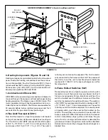
3–Secondary Limit Switches
[(1)S21 and (2)S21]
The secondary limit switches [(1)S21 and (2)S21] on
G25MV units are located in the blower compartment on
the back side of the blower housing (see figure 8). When
excess heat is sensed in the blower compartment, the
limit will open. If the limit is tripped, the burner control
energizes the supply air blower and closes the gas valve.
The limit automatically resets when unit temperature
returns to normal. Two limits are supplied in each furnace
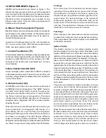
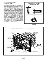
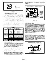
and each limit is a different style. Figure 14 shows both
styles. Both switches are N.C. SPST auto-reset switches
which actuate on a temperature rise. The switches are
factory set and cannot be adjusted. The (1)S21 limit
shown on the top opens at 140
F + 5
F (60.0
C + 2.8
C)
on a temperature rise and closes at 110
F + 10
F (43.3
C
+ 5.6
C). The (2)S21 limit shown on the bottom opens at
165
F + 5
F (73.9
C + 2.8
C) on a temperature rise and
closes at 135
F + 8
F (57.2
C + 4.4
C).
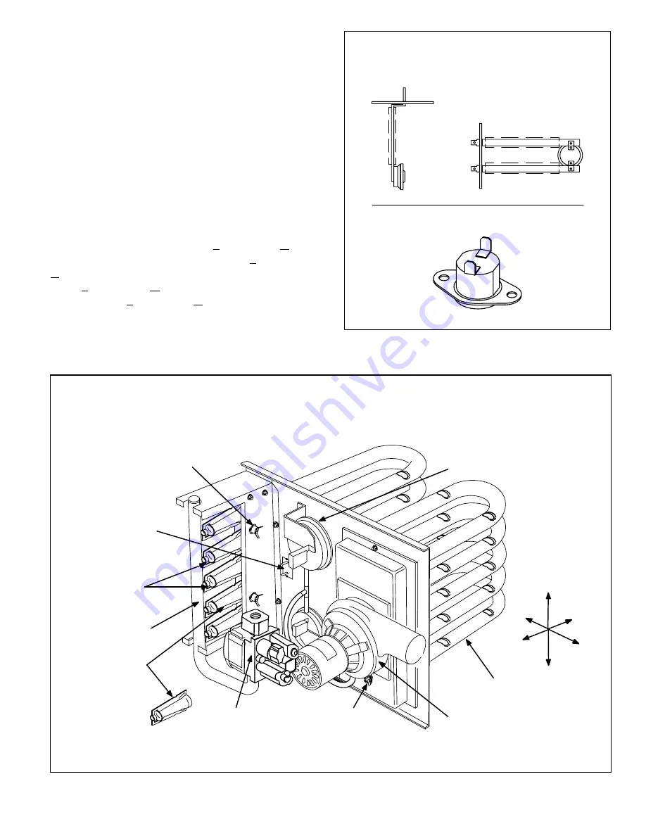
INSULATING COVER (s)
FIGURE 14
SECONDARY LIMIT SWITCHES
FOR G25MV SERIES UNITS
SP
ADE CONNECTORS
INSULA
TING COVER
LIMIT
LIMIT
(1)S21
(2)S21
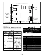
FIGURE 15
HEATING COMPONENTS (shown in horizontal position)
HEAT EXCHANGER
COMBUSTION AIR
BLOWER (B6)
MANIFOLD
ROLLOUT SWITCH (2)
(S47)
COMBUSTION AIR
PROVE SWITCHES
(S72 and S102)
GAS VALVE (GV1)
BURNERS
FLUE LIMIT
THERMOSTAT (S101)
PRIMARY
LIMIT (S10)
ORIFICES
Front
Right
Top
Bottom
Left
Back


