Page 15
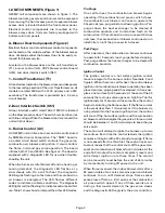
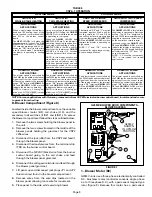
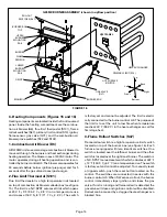
FIGURE 17
ROLLOUT SWITCH (S47)
MANUAL
RESET BUTTON
4–Primary Limit Control (S10)
The primary limit (S10) on G25MV units is located in the
middle of the heating vestibule panel (see figure 16). S10
is the same type of limit as shown on the top of figure 14.
When excess heat is sensed in the heat exchanger, the
limit will open. If the limit is tripped, the burner control
energizes the supply air blower and closes the gas
valve. The limit automatically resets when unit temper-
ature returns to normal. The switch is factory set and
cannot be adjusted. The switch has different setpoints
for each unit model number. See table 7. The setpoint
will also be printed on the side of the limit.
TABLE 7
PRIMARY LIMIT CONTROL (S10)
UNIT
ACTUATE
TEMPERATURE
G25MV3–60
OPEN
200
F + 5
F (93.3
C + 2.8
C)
G25MV3–60
CLOSE
170
F + 8
F (76.7
C + 4.4
C)
G25MV3–75
OPEN
175
F + 5
F (79.4
C + 2.8
C)
G25MV3–75
CLOSE
145
F + 8
F (62.8
C + 4.4
C)
G25MV5–100
OPEN
190
F + 10
F (87.8
C + 5.6
C)
G25MV5–100
CLOSE
160
F + 8
F (71.1
C + 4.4
C)
G25MV5–120
OPEN
150
F + 5
F (65.6
C + 2.8
C)
G25MV5–120
CLOSE
120
F + 8
F (48.9
C + 4.4
C)
5–Gas Valve (GV1)
The G25MV uses a gas valve manufactured by White
Rodgers. The valve is a two-stage internally redundant
to assure safety shut–off. If the gas valve must be re-
placed, the same type valve must be used.
24VAC terminals and gas control knob are located on top
of the valve. All terminals on the gas valve are connected
to wires from the electronic burner control. 24V applied to
the terminals energizes the valve.
Inlet and outlet pressure taps are located on the valve. A
regulator adjustment screw is located on the side of the
valve. Refer to figure 18 for location of valve features.
NOTE–Do not attempt to regulate low fire manifold
pressure.
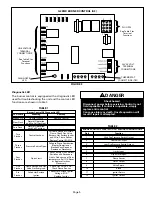
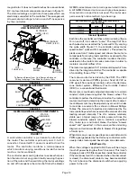
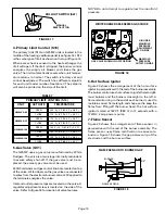
FIGURE 18
WHITE RODGERS 36E SERIES GAS VALVE
GAS VALVE SHOWN IN OFF POSITION
HIGH FIRE
MANIFOLD
PRESSURE
ADJUSTMENT
ON SIDE
MANIFOLD
PRESSURE
OUTLET ON SIDE
6–Hot Surface Ignitor
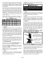
Figure 20 shows the arrangement of the hot surface
ignitor in perspective with the rest of the burner assembly.
The burner control uses hot surface to ignite the two right-
most burners and the burners cross-light to the left. A
flame retention ring in the end of each burner is used to
maintain correct flame length and shape and to keep the
flame from lifting off the burner head. The hot surface
ignitor is rated at 1800
F (982
C) in 17 seconds with a
120VAC 4 amp power source.
7–Flame Sensor
Figure 20 shows the arrangement of flame sensor in
perspective with the rest of the burner assembly. The
flame sensor uses flame rectification to sense com-
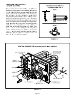
bustion. Figure 19 shows the gap between tip of the
electrode and the burner surface.
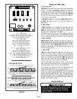
FIGURE 19
FLAME SENSOR TO BURNER GAP
BURNER
FLAME SENSOR
3/4”


