background image

25 


E-Flex User Manual, Rev. 1.30 

Assign Zones to DMX Input 

This feature allows certain zones to be excluded from DMX control from the start address. DMX 
addresses not assigned will be skipped. However the range of DMX addresses controlled by the panel 
will be the same 4 or 8 from the start address set. By default all zones are assigned. 
 
Press 

Menu,


inp1

 menu is displayed. 

Press the 

Up

 button three times to scroll to the 

addr

 menu. 


Press 

Enter

, the 

start address

 entry control is displayed. 

 
Press the 

Up

 button to scroll to the 

zone

 list control.  


Press 

Enter

 to show the first item in the zone list. 

Use the 

Up

 and 

Down

 buttons to scroll thru the list of zones:  


Zon1-4

 – 4 circuit panel 

Zon1-8

 – 8 circuit panel  

 
Press 

Sel

 to assign or un-assign the displayed zone. The apostrophe LED will be lit for each assigned 

zone.  Press 

Store 

button to record the new zone assignments. 

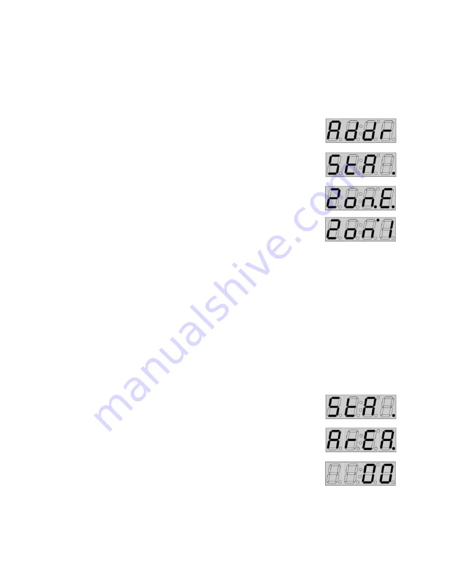
Set DMX Input for Impress Link and Area 

The DMX input port defaults to DMX/RDM mode. It also supports “Impress Link” mode which allows 
Lehigh’s Solitaire or DMX Impress remote stations to recall presets, master levels, and provide room 
combine control using an EFRP. In this mode the EFRP supports area (room) numbering from 1 thru 8 for 
a maximum of eight areas.  
 
Press 

Menu,


inp1

 menu is displayed. 

Press the 

Up

 button three times to scroll to the 

addr

 menu. 

  
Press 

Enter

, the 

start address

 entry control is displayed. 

 
Press the 

Down

 button to scroll to the 

area 

entry


control.  


Press Enter to display current area number. Use the Up and Down buttons to 
change the area. A value of 0 (zero) is DMX/RDM mode; values of 1-8 set the 
primary area number for a room. The default value is 0. 

Press 

Store 

button to record the area number. 


Содержание E-Flex EFRP-04

Страница 1: ...E Flex Installation and User Manual Rev 1 30 F552 13 November 2017 ...

Страница 2: ......

Страница 3: ...actory or 12 months after initial energization of said equipment with the one expiring first given precedence and written notice thereof given to the supplier within 30 days of discovery The sole and exclusive liability of the supplier for Breach of Warranty shall be at its option to replace or repair the product or part concerned F O B its factory or such place as it may designate The warranties ...

Страница 4: ...rminations and Conduit Access 4 Wiring Requirements 5 High voltage Wiring 5 Feed Through Example 4 circuits Individual Feeds 6 Feed Through Example 4 circuits Normal Emergency 120V and 277V Feeds 7 Low Voltage Wiring 7 Low Voltage Side Diagram 8 Input Banks Occupancy Daylight Contact Closure and CapT 9 Demand Response Timeclock Emergency Inputs 9 0 10V Outputs 10 DMX Input 10 E FlexNet 10 Controll...

Страница 5: ...ation 12 Emergency Input 12 Emergency Enable Disable EMERG J12 12 Power Up and Configuration 12 Pre Check 13 Power Up 13 User Interface 14 Menu Navigation 14 Input Programming 15 Occupancy Inputs 15 Navigate to OccX menu 15 Set Mode 15 Set Input Polarity 15 Assign Zones to Occupancy Input 16 Set Occupied Preset 16 Set Un occupied Preset 16 Daylight Sensor Inputs 17 Navigate to DayX menu 17 Set Inp...

Страница 6: ... CapX menu 19 Assign Zones to CapT Input 19 Set CapT Input Preset for 5 button station 20 Emergency Input Programming 21 Assign Zones to Emergency Input 21 Set Emergency Zone Levels 21 TimeClock Demand Response Contact Closure Input Programming 21 Navigate to tcci menu 21 Set Input Polarity 21 Set Timeclock Contact Closure Mode 22 Assign Zones to Timeclock Contact Closure Input 22 Set Timeclock Re...

Страница 7: ...igh End Trim 27 Preset Edit 28 Control Test 29 Navigate to Control menu 29 Clear Memory 29 DMX Loss Behavior 29 Relay Test 30 Ramp Test 30 Relay Override 30 Device ID 31 DASC Daylight Scaler Primary Secondary Daylight Zone Adjustment 31 Default Configuration 32 Input Assignments 32 Occupancy 32 Daylight 32 Contact closure 32 CapT 33 Emergency 33 Timeclock 33 Preset Levels 33 ...

Страница 8: ...4 E Flex User Manual Rev 1 30 DMX Addressing and Zone Assignment 33 Load Setup 33 DMX Loss Behavior 33 RDM Implementation 34 Blank Configuration Chart 35 ...

Страница 9: ...ng relays with the following ratings o Resistive 50A 277VAC 20A 347VAC o Tungsten 20A 240 VAC 277VAC o Standard Ballast 20A 120VAC 277VAC 347VAC Electronic Ballast 16A 120VAC 277VAC 4 or 8 0 10V outputs with current sink of 80mA Integrated 24V DC power supply to provide power for sensors and E FlexNet devices Dry contact closure inputs for UL924 timeclock fire alarm and demand response 4 banks of ...

Страница 10: ...pcoming change After a delay the LightsOut preset will be activated During this delay any button press at any station will further delay the activation of the LightsOut preset Once the LightsOut preset is in effect light levels may be changed by a user After 15 minutes of no inactivity the LightsOut sequence will start again Occupancy Mode Automatically turn lights ON when the occupancy sensor inp...

Страница 11: ...ampering by unauthorized personnel Do not use this equipment for anything but intended use Use of accessory equipment not recommended by the manufacturer may cause unsafe conditions Must be serviced by qualified personnel only SAVE THESE INSTRUCTIONS Warnings and Notices Warning This warning indicates situations where there is a risk of electric shock Warning A warning statement indicates situatio...

Страница 12: ...ertical surface Mount the panel in an accessible location to allow for end use programming or relay bypassing Circuit Breaker Protection Prior to installation of the E Flex relay panel make sure that you have installed a main circuit breaker cabinet or other input power disconnect Warning Without an Accessible power disconnect breaker the E Flex relay panel cannot be operated or serviced safely Te...

Страница 13: ... controller make sure upstream source of power is off Warning A high voltage shield covers the right side of the controller to serve as a mechanical barrier to provide voltage separation inside the panel enclosure of the low voltage wiring from the high voltage wiring This shield must be removed for high voltage termination and must be reinstalled when termination is complete Remove two screws at ...

Страница 14: ...6 E Flex User Manual Rev 1 30 Feed Through Example 4 circuits Individual Feeds Load Wires Two 2 14 AWG to 12 AWG Strip length 3 8 in torque 7 in lbs ...

Страница 15: ...Two 2 14 AWG to 12 AWG Strip length 3 8 in torque 7 in lbs Voltage Barriers Separate Normal Emergency 120V and 277V Warning If more than one power source is supplied to the relay panel a voltage barrier is required by local code The voltage barrier is an accessory sold separately Order Lehigh part number A1678 ...

Страница 16: ...local codes for separation requirements Do not combine Class 2 and Class 1 wiring Low voltage control cables must be run in separate conduit from input power wires Low Voltage Side Diagram 8 circuit panel shown 4 circuit is same connections except for 0 10V outputs 5 thru 8 ...

Страница 17: ...put Banks Occupancy Daylight Contact Closure and CapT 24 12 AWG wires strip length in torque 3 5 lbs CapT station cable run limit 150 ft maximum Demand Response Timeclock Emergency Inputs 24 12 AWG wires strip length in torque 3 5 lbs ...

Страница 18: ...ontrol wiring from controller to last driver Limiting to a voltage drop of 3V maximum will help ensure meeting IEC 60929 Annex E standard for minimum light level at 1V Note additional 0 10V outputs for outputs 5 thru 8 as shown in the low voltage side diagram on page 8 DMX Input 24 12 AWG wires strip length in torque 1 7 lbs E FlexNet 24 12 AWG wires strip length in torque 3 5 lbs ...

Страница 19: ...Load Comments Occupancy Sensor 1 Daylight Sensor 25 CapT 25 DTM606 3 DTM612 4 A unit load is defined as 50mA Note If the total unit loads is greater than the capacity of the EFRP install an LPS 20UL link power supply P N H4017 This is 24V with 20 unit load capacity and 120V 277V AC input Switch Configuration SW1 Daylight Sensor Inputs SW1 Position Daylight Sensor Active Low default Active High 1 D...

Страница 20: ...act that will open upon loss of normal power When the emergency input is activated opened the following can be expected for each output of the relay panel For outputs that are assigned to the emergency input the relay will close and the 0 10V output will be driven to 100 Outputs not assigned to the emergency input will remain at their current level Emergency Enable Disable EMERG J12 Jumper J12 EME...

Страница 21: ...itches and jumpers are set per the installation requirements See section on switch configuration page 11 Power Up Apply power with breaker supplying power to the relay panel Check following LED status indicators Test each contact input and ensure the configured relays respond as expected and the relay status LEDs track the response If DMX is being used to control the relay panel verify operation u...

Страница 22: ...to change the value ex entry control for preset selection A list control will have the first and second digit decimal points lit Press Enter to display the first item in the list This may be a list of options or a list of entry controls If it is a list of options selected items in the list will be indicated by the apostrophe LED being lit If it is a list where only one choice can be selected at a ...

Страница 23: ...is displayed Press Enter the occX menu is displayed Note The user can press the Input button at this time to switch to an occupancy input on a different input bank The menu will advance from occ1 to occ2 thru to occ4 Set Mode Press Enter at the occX menu the options list control is displayed Press Enter for options list The current programmed option will be displayed first Use the Up and Down butt...

Страница 24: ...the displayed zone The apostrophe LED will be lit for each assigned zone Press Store button to record the new zone assignments Set Occupied Preset Press Enter at the occX menu the options list control is displayed Press the Down button twice to scroll to the occupied preset entry control Press Enter The current occupied preset will be displayed Use the Up and Down buttons to set the occupied prese...

Страница 25: ...postrophe LED will be lit for the current selected option Press Store button to record the new setting Note Dip switch SW1 x must also be set to ON for active low OFF for active high Assign a Zone to Daylight Sensor Input Press Enter at the dayX menu the Polarity list control is displayed Press the Up button to scroll to the zone list control Press Enter to show the first item in the zone list Use...

Страница 26: ...isplayed option The apostrophe LED will be lit for the current selected option Press Store button to record the new setting Set Contact Closure Mode Press Enter at the cciX menu the Polarity list control is displayed Press the Up button to scroll to the options list control Press Enter for options list The current programmed option will be displayed first Use the Up and Down buttons to display the...

Страница 27: ...croll to the cci preset entry control Press Enter The current CCI preset will be displayed Use the Up and Down buttons to set the occupied preset 1 16 or OFF The default is preset 1 Press Store button to record the new setting OFF preset is only available for mode option 2 CapT Station Inputs Navigate to CapX menu Press Menu inpX menu is displayed Press Enter the occX menu is displayed Press the D...

Страница 28: ...he new zone assignments Set CapT Input Preset for 5 button station Press Enter at the capX menu the zones menu is displayed Press the Up button to scroll to the capT preset entry control Press Enter The current CapT preset will be displayed Use the Up and Down buttons to set the occupied preset 1 16 The default is preset 1 Press Store button to record the new setting ...

Страница 29: ...evels for preset 17 default to 100 The levels for the zones assigned to the emergency input can be adjusted by going to the preset edit menu and selecting preset 17 See that section on how to adjust preset levels TimeClock Demand Response Contact Closure Input Programming Navigate to tcci menu Press Menu inpX menu is displayed Press the Up button twice to scroll to the tcci menu Set Input Polarity...

Страница 30: ...ng preset 19 is dedicated to panic preset for time clock use preset editor to set levels as desired Assign Zones to Timeclock Contact Closure Input Press Enter at the tcci menu the Polarity list control is displayed Press the Up button twice to scroll to the zone list control Press Enter to show the first item in the zone list Use the Up and Down buttons to scroll thru the list of zones Zon1 4 4 c...

Страница 31: ...ore button to record the new setting Set Demand Response Load Shed Values Each zone can be independently set with its own load shed value This sets the DR maximum level for a zone as 100 load shed value Press Enter at the tcci menu the Polarity list control is displayed Press the Down button to scroll to the tcci demand response menu item Press Enter The tcci demand response fade time entry contro...

Страница 32: ...k and remote setting of DMX starting addresses as well as status and fault reporting back to a controller The E Flex relay panel supports discovery and remote start address setting The E Flex relay panel can be controlled by any DMX based system theatrical or architectural It is compatible with Lehigh s own Solitaire and DMX Impress architectural controls The user has the option of setting a DMX s...

Страница 33: ...he displayed zone The apostrophe LED will be lit for each assigned zone Press Store button to record the new zone assignments Set DMX Input for Impress Link and Area The DMX input port defaults to DMX RDM mode It also supports Impress Link mode which allows Lehigh s Solitaire or DMX Impress remote stations to recall presets master levels and provide room combine control using an EFRP In this mode ...

Страница 34: ...e new setting receptacle type ignores daylight sensor input also high and low end trim Set Low End Trim and relay cutoff Press Menu inpX menu is displayed Press the Down button three times to scroll to the load menu Press Enter to display the zone select menu Use the Up and Down buttons to select a zone to setup Press Enter the type list control is displayed Press the Up button to scroll to the tr...

Страница 35: ...ttons to select a zone to setup Press Enter the type list control is displayed Press the Up button to scroll to the trim menu Press Enter the low end entry control is displayed Press the Up button to scroll to the high end entry control Press Enter The current value will be displayed Use the Up and Down buttons to set the trim between 55 and 100 The default is 100 Press Store button to record the ...

Страница 36: ...ight two digits show the current zone level 0 99 and FL full 100 Use the Sel button to switch between selecting a zone L1 8 and changing the zone level Two decimal points act as a cursor for each digit pair to indicate which can be changed using the Up and Down buttons Use the Up and Down buttons to select the zone L1 8 Press Sel to switch to level edit Use the Up and Down buttons to change the le...

Страница 37: ...o show the first item in DMX loss options list The current programmed option will be displayed first Use the Up and Down buttons to display the available options Opt1 None return control to other inputs default Opt2 Go to off Opt3 Go to 100 Opt4 Go to preset 18 Press Sel to choose the displayed option The apostrophe LED will be lit for the current programmed option Press Store button to record the...

Страница 38: ...r memory menu is displayed Press the Up button thrice to display the ramp menu Press Enter to start ramp test loops thru each output ramping to full then off The ramp test screen indicates the current output that is ramping Press Menu to exit and end ramp test Relay Override Use relay override to turn on zone relay bypassing all inputs Relay status LEDs will reflect the override state Press Enter ...

Страница 39: ...hen using one photocell to control more than one daylight zone Typically the primary daylight zone is closest to a window secondary daylight zones are farther away so will require more light from the luminaire This menu lets you reduce the effect of the daylight sensor photocell on a zone by scaling the dimming from the photocell Press Enter at the control menu the Clear memory menu is displayed P...

Страница 40: ...auto off Polarity active high Unoccupied Preset Off Daylight Input Zone 1 Zone 2 Zone 3 Zone 4 Zone 5 Zone 6 Zone 7 Zone 8 day1 X day2 X day3 X day4 X Polarity Active low Contact closure Input Zone 1 Zone 2 Zone 3 Zone 4 Zone 5 Zone 6 Zone 7 Zone 8 cci1 X cci2 X cci3 X cci4 X Polarity NO Mode Opt4 maintained closure turns on assigned zones to preset open to off Assigned Preset for mode operation 1...

Страница 41: ...turns on assigned zones to preset if open to off Assigned Preset for mode operation 1 Preset Levels 1 100 5 16 100 2 75 17 Emergency 100 3 50 18 DMX Loss 0 4 25 19 Timeclock opt 4 100 DMX Addressing and Zone Assignment Default Start Address 001 Zone 1 Zone 2 Zone 3 Zone 4 Zone 5 Zone 6 Zone 7 Zone 8 1 2 3 4 5 6 7 8 Load Setup Zone 1 Zone 2 Zone 3 Zone 4 Zone 5 Zone 6 Zone 7 Zone 8 Type 0 10V 0 10V...

Страница 42: ...s Get Set DMX Start Address Get Set Identify Device The following RDM features are implemented in the E Flex relay panel beyond those required by the specification Get Product Detail List Get Device Model Description Get Manufacturer Label Get Device Label Get Software Version Label ...

Страница 43: ...iguration Chart Input Zn 1 Zn 2 Zn 3 Zn 4 Zn 5 Zn 6 Zn 7 Zn 8 Pol Mod e Preset s Area occ1 N A occ2 occ3 occ4 day1 N A day2 day3 day4 cci1 cci2 cci3 cci4 cap1 N A cap2 cap3 cap4 Emerg N A N A TC DmdR esp Dmd Rsp N A DMX N A Impress Link Load Type N A N A High Trim Low Trim ...

Отзывы: