background image

3

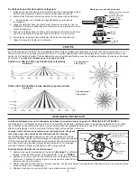
COVERAGE PATTERN

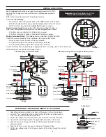
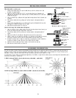
The CI-300 provides a 360° coverage pattern. Two lens patterns are available. The CI-300 provides up to 1200 square feet of coverage and 

the CI-300-1 provides up to 500 square feet of coverage. The coverage shown represents walking motion at a mounting height of 8 feet. For 

building spaces with lower levels of activity or with obstacles and barriers, coverage size may decrease.


8’ (2.4m)

10’ (3m)

12’ (3.7m)

0

40’

(12.2m)

30’

(9.1m)

20’

(6.1m)

10’

(3m)

40’

(12.2m)

30’

(9.1m)

20’

(6.1m)

10’

(3m)

0

8’ (2.4m)

10’ (3m)

12’ (3.7m)

0

20’

(6.1m)

15’

(4.6m)

10’

(3m)

5’

(1.5m)

0

20’

(6.1m)

15’

(4.6m)

10’

(3m)

5’

(1.5m)

24 ft

7.3m

IW

P

Top View @ 8ft

Top View @ 8ft

C-300 Coverage Pattern (Extended Range Lens – Standard)

C-300 Coverage Pattern (High Density Reduced Range Lens)

Side View

Side View

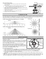
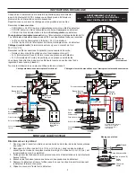
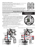
Using an Octagonal J-Box

1.  Pull the low voltage wires from the power pack into the J-Box through the 

conduit knockout.

2.  Connect the low voltage wires to the appropriate terminals on the sensor.
3.    Loosen the appliance mounting screws attached to the J-Box
4.  Align the sensor in the J-Box so that the mounting screws on the box match 

the key holes on the sensor’s rear housing.

5.  Push the sensor up into the J -Box and twist it so that the mounting screws are 

seated in the keyhole slots.

6.  Tighten the two screws to secure the sensor to the J-Box.
7.  Snap the front cover onto the sensor.

Rear

Housing

Depluggable

Terminal

4" Octagonal J-Box 

(at least 1.5" deep)

Front

Cover

Ceiling

Screws

J-Box Mount

SENSOR ADJUSTMENT

This unit is pre-set for basic operation as described in this guide. 

Adjustment is optional. 

The sensors are factory preset to allow for quick installation in most applications. 

Verification of proper wiring or coverage, or customizing the sensor’s settings 

can be done using the following procedures. To make adjustments, open the 

Front Cover by pulling on the cover tab.

There is a 30 second warm-up period when power is first applied.

Before making adjustments, make sure the office furniture is installed, lighting 

circuits are turned on, and the HVAC systems are in the overridden/on position. 

VAV systems should be set to their highest airflow. Set the DIP switches to the 

desired settings. See 

DIP Switch Setting

, next page.

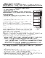
To Test Occupancy Sensors

1.  Ensure the Time Delay is set for 

Test Mode*

 using the “Test Mode/20 minutes” setting. (DIP switches 1,2, & 3 are 

OFF

). 

2.  Ensure that the Light Level is at default (maximum). See the Light Level Feature section of this document for instructions.

3.  Remain still. The red LED should not flash. The lights should turn off after 5 seconds. (If not, see 

Troubleshooting

.)

4.  Move about the coverage area. The lights should come on. 

5.  When testing and adjustment are complete, reset DIP Switches and Light Level to the desired settings, and replace the cover on 

the sensor.

* Test Mode

 is a temporary state that starts when you first set the sensor’s DIP switches for the “Test Mode/20 minutes” (switches 1, 2,  

  3, 

OFF

). If you need to invoke the 

Test Mode

 and the DIP switches are already set for Test Mode/20 minutes, toggle DIP switch 1 

ON


  then back to the 

OFF

 position. This provides a 10 minute test period. During the test period, the Time Delay is only 5 seconds.

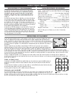
.H\KROHVORWV

IRUPRXQWLQJWR

RFWDJRQDOER[

'RXEOHJDQJ

PXGULQJ

PRXQWLQJKROHV

/LJKWOHYHO

SXVKEXWWRQ

',3

VZLWFKHV

3,5OHQV

21

(&(

3,5$FWLYLW\

/('5HG

Содержание Wattstopper CI-300

Страница 1: ...temperatures may cause false activations Mount the sensor to the ceiling The CI 300 sensors are designed for a ceiling height of about 8 10 feet Mounting above or below this range will significantly affect the coverage patterns Be aware that as you decrease the mounting height you decrease the range and increase the sensitivity to smaller motions Conversely when you increase the height you increas...

Страница 2: ...er Class 2 Power Packs For Indoor Use Only LISTED www legrand us wattstopper Relay Com N O N C Control Out Man Switch 24V Common v5 Wiring terminals Load 1 Load 2 Optional CI 300 Rear Housing Depluggable Terminal Front Cover Ceiling Spring Clips 2 Blue Control Out 24V Common Low Voltage Class 2 Line Voltage Line Neutral Feed Through Power Pack Black Red 1 2 Line Voltage Switches Standard wiring wi...

Страница 3: ...is optional The sensors are factory preset to allow for quick installation in most applications Verification of proper wiring or coverage or customizing the sensor s settings can be done using the following procedures To make adjustments open the Front Cover by pulling on the cover tab There is a 30 second warm up period when power is first applied Before making adjustments make sure the office fu...

Страница 4: ...hanged DIP SWITCH SETTING The CI 300 has 7 DIP switches under the cover Time Delay Switches 1 2 3 The sensor will hold the lights ON as long as occupancy is detected The time delay countdown starts when no motion is detected After no motion is detected for the length of the time delay the sensor will turn the lights OFF Walk Through Switch 4 Walk through mode turns the lights OFF three minutes aft...

Страница 5: ...o not turn OFF automatically 1 The sensor technology PIR may be experiencing activations from outside the controlled area or from some type of interference see Unwanted Sensor Activations below 2 Check all sensor and power pack wire connections 3 Disconnect power pack s blue wire If the lights do not turn off replace power pack Reconnect blue wire If the lights turn off the problem may be in the s...

Страница 6: ...nts À l inverse lorsque vous augmentez la hauteur vous augmentez la portée et diminuez la sensibilité aux petits mouvements À des hauteurs supérieures à 3 7 4 3 m 12 14 pi vous commencez à réduire la sensibilité de manière significative En règle générale chaque occupant doit être capable de voir clairement le détecteur Souvent l emplacement idéal d un CI 300 dans un bureau fermé est excentré Évite...

Страница 7: ...pper Relay Com N O N C Control Out Man Switch 24V Common v5 Bornes de raccordement AVERTISSEMENT COUPER LE COURANT AU DISJONCTEUR PRINCIPAL AVANT D INSTALLER LE CÂBLAGE Câblage standard avec interrupteur d arrêt local Câblage de la marche manuelle avec un interrupteur instantané basse tension Charge 1 Charge 2 en option CI 300 Boîtier arrière Borne débranchable Couvercle frontal Plafond Clips à re...

Страница 8: ... Couvercle frontal Plafond Vis Montage avec une boîte de jonction RÉGLAGE DU DÉTECTEUR L unité est préréglée pour un fonctionnement de base comme décrit dans ce guide LE RÉGLAGE EST OPTIONNEL Les détecteurs sont préréglés en usine afin de vous permettre de l installer rapidement dans la plupart des applications Pour vérifier que le câblage ou la portée sont corrects ou pour personnaliser les régla...

Страница 9: ...ité des occupants Une fois la temporisation écoulée si aucun mouvement n est détecté pendant la période de redéclenchement de 30 secondes l interrupteur manuel doit être utilisé pour remettre la charge en MARCHE Automatique MARCHE ce mode se sert des déclenchements dus à la présence ainsi que de l activation de l interrupteur pour ACTIVER la charge Un interrupteur manuel fournit les fonctionnalité...

Страница 10: ... Vérifiez que le disjoncteur de circuit a bien été réenclenché 2 Vérifiez tous les raccordements des fils du détecteur et du bloc d alimentation 3 Vérifiez que le capteur est raccordé à une tension de 24 V Si du 24 V est bien présent remplacez le détecteur Si vous ne trouvez pas de 24 V vérifiez la présence de haute tension au niveau du bloc d alimentation Si c est le cas remplacez le bloc d alime...

Страница 11: ...r los paquetes de alimentación Wattstopper de 24 V CA o CA de media onda rectificada Los sensores CI 300 también tienen un relé aislado con contactos Normalmente abierto N A y Normalmente cerrado N C para acoplarse con el sistema de calefacción ventilación y aire acondicionado HVAC o el sistema de administración de energía EMS GUÍAS PARA LA COLOCACIÓN Según los obstáculos como muebles o divisiones...

Страница 12: ...minal de 24 del sensor El cable del otro lado del interruptor a la terminal de interruptor man del sensor Cableado del relé aislado El relé aislado es apto para 1 A a 30 V CA V CC Conecte los cables necesarios para la aplicación que requiere esta salida Relé común se debe usar para el funcionamiento adecuado Normalmente abierto N A se cierra cuando se detecta una presencia Normalmente cerrado N C ...

Страница 13: ...para que los tornillos de montaje se inserten en las ranuras de los orificios tipo bocallave 6 Apriete los dos tornillos para fijar el sensor a la caja de conexiones 7 Encastre la cubierta frontal en el sensor ORMDPLHQWR WUDVHUR 7HUPLQDO GHVHQFKXIDEOH XELHUWD IURQWDO LHOR UDVR EUD DGHUDV GH UHVRUWH Montaje en techo Alojamiento trasero Terminal desenchufable Caja de conexiones octágonal de 4 al men...

Страница 14: ...rante el día cuando la luz ambiente en el área esté en el nivel deseado El nivel de luz no se puede activar mientras esté activo el modo de prueba Espere a que finalice el modo de prueba o seleccione cualquiera de las configuraciones adicionales de demora de tiempo antes de activar la función de nivel de luz El indicador LED de presencia PIR quizás aún responda cuando las luces se mantienen apagad...

Страница 15: ...omo la activación mediante interruptor para encender la carga Un interruptor manual proporciona la siguiente funcionalidad adicional 1 La carga puede encenderse con la activación del interruptor manual y permanece encendida según la configuración de lógica de presencia La demora de tiempo del sensor funciona según lo programado Cuando la carga se apaga a causa de la falta de detección de presencia...

Страница 16: ... algún tipo de interferencia consulte Activaciones no deseadas del sensor a continuación 2 Controle todas las conexiones de cables del sensor y de la fuente de alimentación 3 Desconecte el cable azul de la fuente de alimentación Si las luces no se apagan reemplace la fuente de alimentación Vuelva a conectar el cable azul Si las luces se apagan el problema puede estar en el sensor Para comprobar Vu...

Отзывы: