60
®
INDICATION
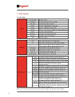
Press ENTER to change the X value and consequently vary the power module from where you read data.
7. Control panel
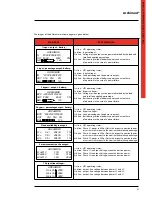
PM status
PM
Measure-
ments
Battery X
Voltage
Voltage measured at the ends of the batteries by the
power module X [V]
Current
Current required to the batteries from the power
module X (negative if the batteries are being charged) [A]
Batt. Charger Status of the battery charger inside module X
Misc. X
INV. dissip.
Temp.
Temperature of the INV dissipater (Inverter) of the power
module X [°C]
BST dissip.
Temp.
Temperature of the Booster /PFC dissipater of
the power module X [°C]
Fan speed
Fan speed expressed as a percentage of the power module X
HV Bus pos. Voltage on the DC BUS positive of the power module X [V]
HV Bus neg. Voltage on the DC BUS negative of the power module Xm [V]
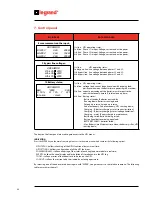
PM
Historical
Data
X
Run Time
Total time working
Battery time
Total time running on battery
BattCharg Time Total time the battery charger has been working
Bypass int.
Total number of Bypass interventions
Battery int.
Total number of battery interventions
Dumper int.
Total number of Dumper interventions
T mains high
Total number of times the input mains voltage has exceeded the
maximum value allowed by the power module
No.Overheat.
Total number of overheatings
No. Overloads Total number of overloads
No. HV Bus run Total number of overvoltages on the Bus
No. Out DC Level Total number of continuous voltage presences in output from the PMs
Diagnostics (*)
Reset PM
Errors
Deletes the memory of errors found in the power module.
Resets only resettable errors.
PM SW
update (*)
Update all
the PMs
It allows the sequential and automatic updating of the internal
software of all the UPS power modules. Press “ENTER” to start the
procedure. If the update is unnecessary the following message
appears on the display:
“PM SW versions updated!” Press “ESC” to exit the frame.
Update a single
PM
It allows the updating of the internal software of a single power
module. Using the “ARROW” keys you select the module you wish to
update (‘PM00’ indicates the module at the top on the left, going on to
the last one at the bottom on the right).
By pressing “ENTER” key a frame appears that gives a comparison
between the software that is actually in the module selected and the
software you are about to load. Press “ENTER” to start the update
procedure.
Once updated, the message “PM SW version updated!” appears on
the display. Press “ESC” to exit the frame.
(*) Available in the “Service Mode” only
Содержание Archimod
Страница 1: ...Archimod Operating and Maintenance Manual Part LE05755AA 09 12 01 GF ...
Страница 2: ...Archimod 2 EN ENGLISH 3 ...
Страница 13: ...Archimod Operating and maintenance manual 13 3 3 Models UPS Archimod 20 18U UPS Archimod 20 UPS Archimod 40 ...
Страница 14: ...14 3 Technical description UPS Archimod 60 UPS Archimod 80 UPS Archimod 100 ...
Страница 15: ...Archimod Operating and maintenance manual 15 UPS Archimod 120 UPS Archimod Battery ...
Страница 81: ...81 Archimod ...
Страница 82: ...82 ...
Страница 83: ......

