Archimod®
Oper
ating and main
tenanc
e manual
47
6.2.12 Wiring
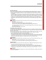
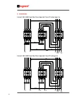
An opening in the base of the UPS is for passing the cables through and there are also some fixing points for the cables.
It is essential to secure the cables firmly after they have been connected to the equipment.
6.2.13 Emergency Power Off (Remote E.P.O.)
In accordance with the standards, the UPS is fitted with an emergency device arranged to use a normally closed external
contact that can be opened to activate the emergency machine power off.
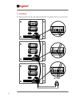
The E.P.O. terminals are in the UPS’s rear panel on pins 3 and 4 of the 6-pole Combicon connector installed on all contact
interfaces (see 3.5.2).
If there is more than one contact interface, connect the E.P.O terminals on each contact interface as follows:
1. connect the E.P.O. terminals of all the contact interfaces in parallel (pin 3 with pin 3, pin 4 with pin 4).
2. close the parallel created on the n.c. contact of the emergency power off device.
To connect the emergency-power-off device correctly please follow these instructions:
- use a cable with double insulation, no more than 10 metres in length.
- check that the switch used is galvanically insulated.
Electrical specifications of the E.P.O. interface:
- Voltage between terminals 3 and 4 (6P Combicon) with open circuit = 12Vdc.
- Current between terminals 3 and 4 (6P Combicon) with closed circuit = 5mA.
Содержание Archimod
Страница 1: ...Archimod Operating and Maintenance Manual Part LE05755AA 09 12 01 GF ...
Страница 2: ...Archimod 2 EN ENGLISH 3 ...
Страница 13: ...Archimod Operating and maintenance manual 13 3 3 Models UPS Archimod 20 18U UPS Archimod 20 UPS Archimod 40 ...
Страница 14: ...14 3 Technical description UPS Archimod 60 UPS Archimod 80 UPS Archimod 100 ...
Страница 15: ...Archimod Operating and maintenance manual 15 UPS Archimod 120 UPS Archimod Battery ...
Страница 81: ...81 Archimod ...
Страница 82: ...82 ...
Страница 83: ......


